Other wall install options include using the:
• MBO-ART03 bracket
Note
You can use the MBO-ART02 bracket if you have one.
The MBO-ART02 wall mount bracket is End of Sale (EOS) as of January, 2023.
It is replaced by the MBO-ART03 bracket.
The following hardware is required when installing the access point on a at surface
using the KT-147407-02 bracket:
• One access point
• Flat part of the KT-147407-02 bracket with two holes on the metal surface (see Flat
part of the KT-147407-02 bracket).
• 1-axis tilt bracket (see Figure 6 on page 23).
• KT-150173-01 extension arm (see Figure 7 on page 24).
• Six M6 screws
• Four M6 size hex-head screws
• Screw-in anchors if the access point is being mounted on a wood wall or a concrete
surface.
Note
The M6 hex-head screws and screw-in anchors must be provided by the
installer.
If you install the access point to the wall using the ART03 bracket, use the following
hardware:
• One access point
• MBO-ART03 articulating mounting bracket
• Six M6 hex-head screws
◦ Two M6 hex-head screws to attach the bracket to the access point
◦ Four M6 hex-head screws to attach the bracket to the wall or a at surface.
Note
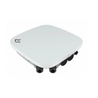
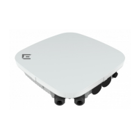
The cable glands must face down when you install the access point on a wall.
Install the Access Point on a Wall Install the Access Point
18 ExtremeWireless™ AP560h Access Point
 Loading...