Chapter 1: Summit Family Switches
Summit Family Switches Hardware Installation Guide
134
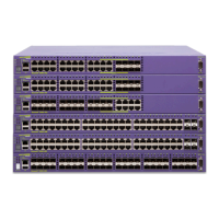
Figure 112: Summit X750 Rear Panel
Summit X750 Series Switch LEDs
Table 36 describes the LEDs on the Summit X750 series switches.
Table 37: LEDs on the Summit X750 Series Switches
Label or Type Color/State Meaning
Front Panel LEDs
M (Management) Steady green Power-on self test (POST) has finished.
Normal operation
Blinking green POST in progress
Blinking amber POST failed.
Off No external power is attached.
FAN
1, 2, 3, 4, 5
Steady green Normal operation
Blinking amber Failure
Off No power
P1, P2
(Power Supply)
Steady green Normal operation
Steady amber Power is attached, but no power is on.
Blinking amber Power failure
Off No power is attached.
Ethernet Ports 40G mode
1, 5, 9, 13, 17, 21, 25, 29,
33, 37, 41, 45, 49, 50 51,
52, 53, 57, 61, 65, 69, 73,
77, 81, 85, 89, 93, 97,
101, 102, 103, 104
Steady blue Link OK
Blinking blue Activity
Off No link or port disabled.
Ethernet Ports 10G mode
1 – 104
Steady green Link OK
Blinking green Activity
Off No 10G link or port disabled.
2-digit Stack number Indicator
Left digit (1) Reserved for future use.
3
1
2
4
1 = Fan modules
2 = Power Supply Unit
3 = Blank power supply slot
4 = Timing cable connectors

 Loading...