Summit X440 Series Switches
Summit Family Switches Hardware Installation Guide
63
Figure 40: Summit X440-24p Switch Rear Panel
Summit X440-24x Switch
The front panel of the Summit X440-24x switch (Figure 41) includes:
● 24 unpopulated SFP ports (ports 1–24) that provide 24 Gbps of fiber connectivity. The SFP ports
support both 100BASE-FX and 1000BASE-X optical modules.
Ports 21 through 24 are implemented as shared ports that pair a copper port with a fiber port. For
more information about combination ports, see “Combination Ports and Failover” on page 22.
For information about SFPs, see the Extreme Networks Pluggable Interface Modules Installation Guide.
● Four autosensing 10/100/1000BASE-T ports (ports 21–24) that provide 4 Gbps of high-density
copper connectivity.
These ports are implemented as shared ports that pair a copper port with a fiber port. For more
information about combination ports, see “Combination Ports and Failover” on page 22.
● Ethernet management port
● Serial console port implemented as an RJ-45 connector, used to connect a terminal and perform local
management
● LEDs to indicate port status and switch operating conditions
For a description of the LEDs and their operation, see “Summit X440 Series Switch LEDs” on
page 77.
● Stack number indicator
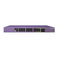
Figure 41: Summit X440-24x Switch Front Panel
1 = AC power input connector
2 = Stacking ports
3 = Redundant power connector
3
SH_266
2
1
X
4 5 6
321
1 = Ethernet management port
2 = SFP ports
3 = 10/100/1000BASE-T ports
4 = Stack number indicator
5 = Console port
6 = Combination ports

 Loading...