MLC Plus 50/100/200 Series • Hardware Features and Installation 27
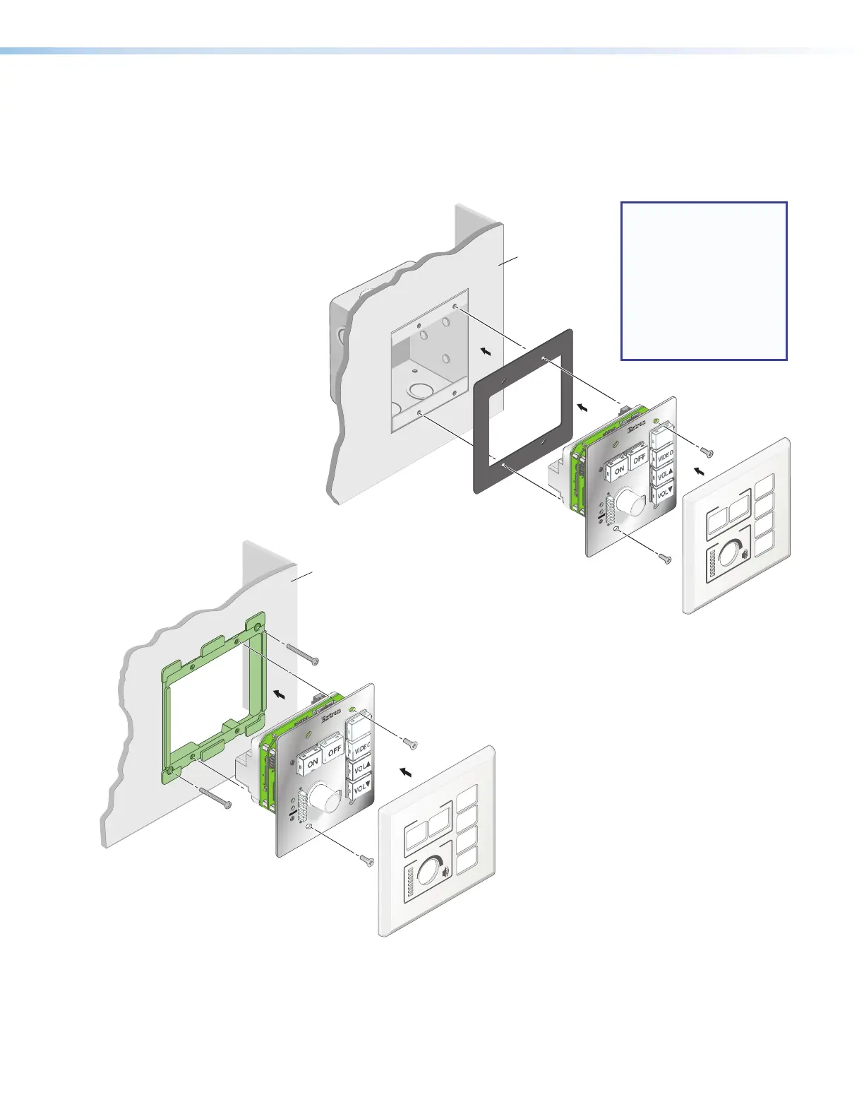
4. For non‑AAP models, secure the MLCPlus to the junction box, wall or surface
mounting box, or mud ring as follows (see figures 27 and 28,
4
):
a. Insert the included screws through the oval slots at the top and bottom of the
MLCPlus, through the plastic spacer (if not using a mud ring), and into the
corresponding threaded holes in the box or mud ring.
b. Using a Phillips
screwdriver, lightly
tighten the
screws until
snug.
E
E
PC
Extron
DISPLAY
VOLUME
44
Wall
Wall
Faceplate
MLC Plus 100
Plastic Spacer
Figure 27. Installing the MLCPlus
in a Junction Box
E
E
PC
Extron
DISPLAY
VOLUME
55
4
4
Wall
MLC Plus 100
Wall Mounting
Bracket
Faceplate
Figure 28. Installing the MLCPlus
in a Mud Ring
NOTE: If the unit is not
installed in a mud
ring, you must install
the plastic spacer.
The spacer positions
the unit to allow the
magnetic faceplate
to attach properly
and securely.
5. Attach the faceplate to the MLCPlus: align the faceplate openings with the buttons, knob,
and LEDs, and place the faceplate against the unit (see figures 26, 27, and 28,
5
). The
magnetic catches fasten the faceplate onto the front of the unit.