Page 41 of 77
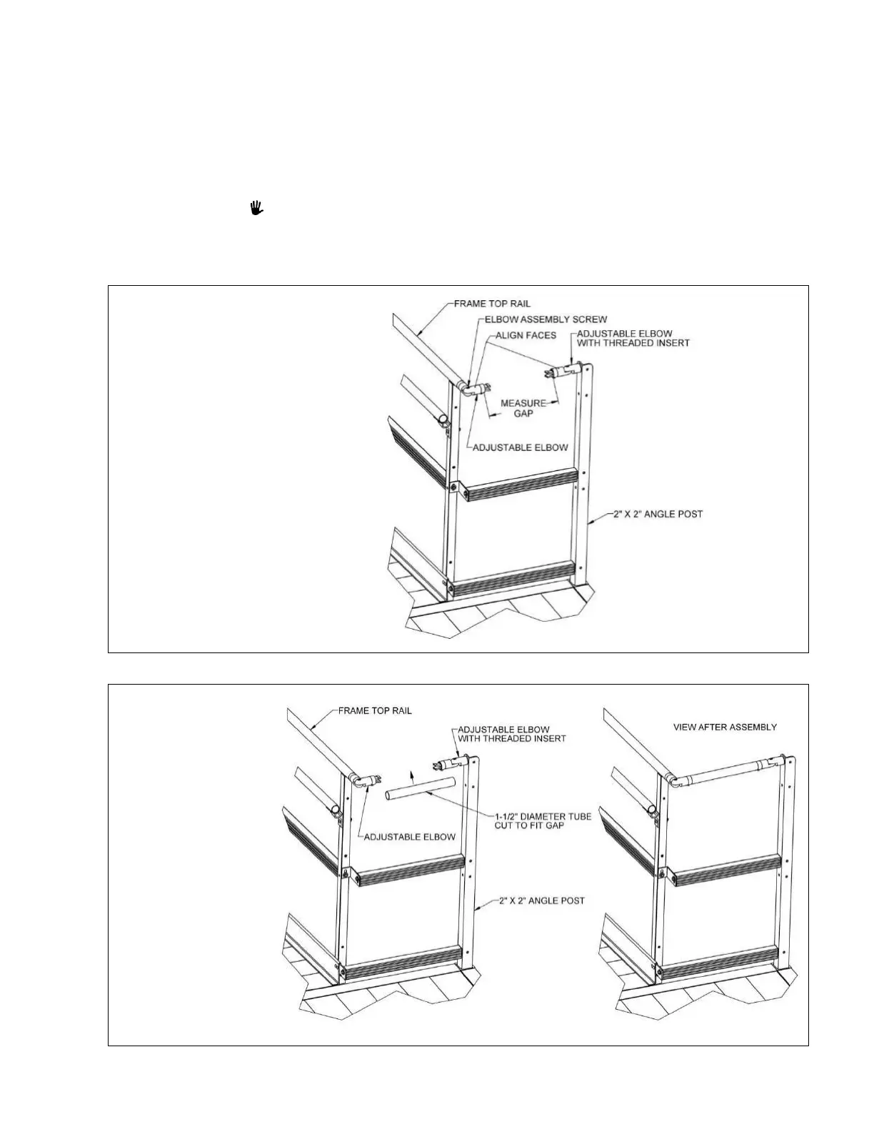
5.4.5. Loosen the elbow assembly screws and align the round faces of the adjustable elbows,
then tighten the elbow assembly screws and joiner set screws enough to hold them in
position (FIG. 5.11).
5.4.6. Measure the gap between the faces of the opposing rings of the 2-15/16” ring joiners
(FIG. 5.11).
5.4.7. Cut the 1-1/2″ diameter round tube to the length measured.
5.4.8. Using a metal file, smooth any sharp edges from cutting.
5.4.9. Install the cut 1-1/2″ diameter round tube between the 2-15/16” ring joiners.
To facilitate assembly you will need to remove and reinstall the adjustable elbow with
threaded insert from the 2” x 2” angle post (FIG. 5.12).
5.4.10. Tighten the adjustable elbow assembly screws and all 2-15/16” ring joiner set screws
securely.
 Loading...