23
Figure 22. UL model setting
─
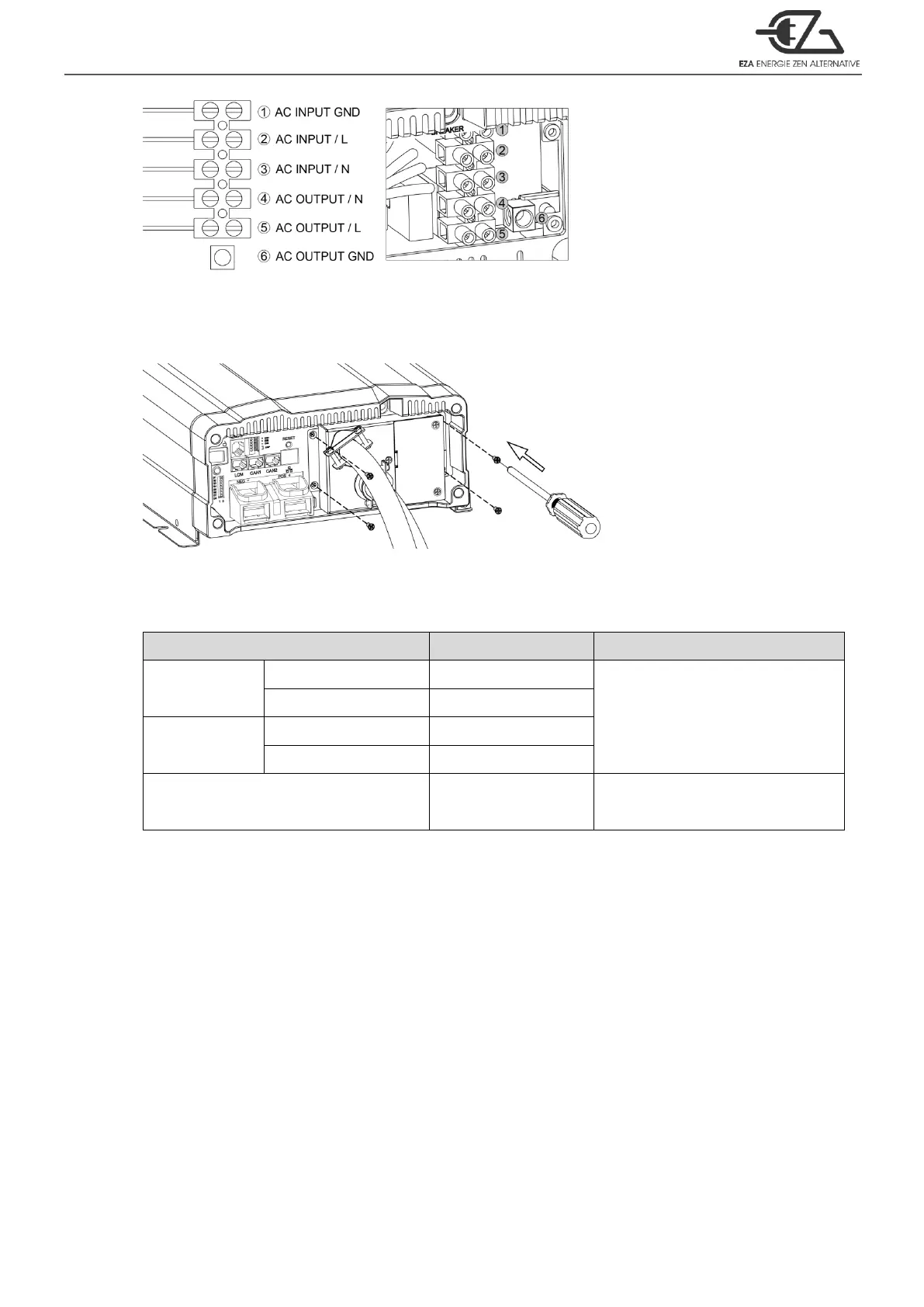
AC wiring
Step 3.
Use the screwdriver to fix the cover.
Figure 23. UL model setting
─
Step 3
4-2-2. Connect AC output and AC input wiring to the ECB series terminals.
Please take the following information as your reference.
Table 17. Wire Color / Wire Length / Wire Gauge
CAUTION!
It is advised that all the electrical installation should conform to the local electrical
codes and should be carried out by a certified technician.
When the unit is feeding the internally inverted voltage, the current carrying
conductors connected to the “L” and “N” terminals of the AC output will be isolated
from the metal chassis of the inverter. Hence, during this condition, when the metal
chassis of the inverter is connected to the earth ground, the “N” terminal of the AC
output will not be grounded (bonded) to the earth ground. Under this condition, the
“N” terminal of the AC output will not be a Neutral in the true sense. Do not touch this
terminal as it will be at an elevated voltage (almost half the value the AC output
voltage) with respect to the metal chassis / earth ground and may produce an
electrical shock when touched!