Chapter 5
5 - 2
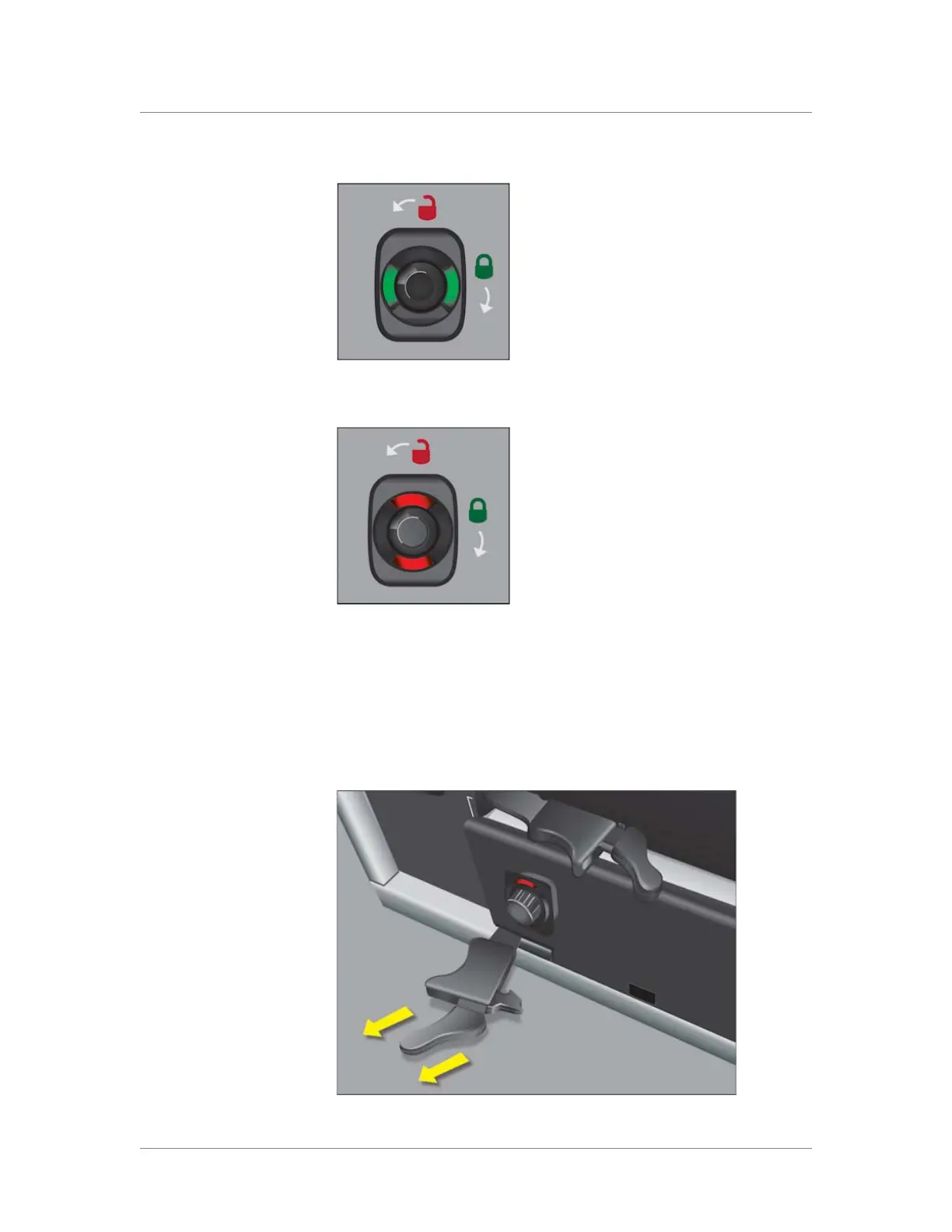
Figure 5.1 A compression screw in the green (locked) position
Figure 5.2 A compression screw in the red (unlocked) position
3. Grasp the two eject levers on the front of the blank and pull towards
you as shown in Figure 5.3.
You can now remove the blank from the slot, and add the new
blade.
Figure 5.3 Extending an eject lever