46
746 E R 32 732099 - Rev.D
60 W max
61415 13
M
L
N
MOT COM
MOT1
LAMP
2.5
J6
Translation of the original instructions
ENGLISH
9. PUTTING INTO SERVICE
RISKS
PERSONAL PROTECTIVE EQUIPMENT
F
Disconnect the power supply to the system before removing the cover of the
board. Only remove the board cover in order to work on electrical connec-
tions. Only reconnect the power supply after having reinstalled the cover.
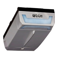
10.1 FLASHING LIGHT
The flashing light indicates that the automation is moving. If pre-
flashing is enabled, it starts 5 s before movement begins.
Use a 230 V~ flashing light with a max load of 60 W.
1. Install the flashing light in a position that is easily visible from
inside and outside the property.
2. Connect to the LAMP terminals on J6 (46).
3. Program the pre-flashing. Function PF in Advanced program-
ming:
PF = no no pre-flashing
PF = oP pre-flashing only before opening
PF = CL pre-flashing only before closing
PF = OC pre-flashing before any movement
TERMINAL BOARD J6
13 LAMP L Phase
14 LAMP N Neutral
10. ACCESSORIES
9.1 FINAL OPERATIONS
RISKS
PERSONAL PROTECTIVE EQUIPMENT
1. Make sure that the forces generated by the leaf are within the limits
permitted by the current regulations. Use an impact force tester
in accordance with standard EN 12453. For non-EU countries, if
there are no specific local regulations, the static force must be less
than 150 N. If necessary, adjust the anti-crushing system and the
sensitivity of the obstacle detection system.
2. Make sure that the maximum force required to move the leaf manu-
ally is less than 225 N in residential areas and 260 N in industrial
or commercial areas.
3. Highlight all areas with adequate warning signs in which there are
still residual risks, even if all possible safety measures having been
adopted.
4. Place a “DANGER, AUTOMATIC MOVEMENT” sign (not supplied) in a
prominent position on the gate.
5. Attach the CE marking to the gate.
6. Fill out the EC declaration of conformity and the system register.
7. Give the EC Declaration, the system register with the maintenance
plan and the instructions for use of the automation to the system
owner/operator.