26
c
230/115
d
B
A
e
14A START-UP OF THE AUTOMATED SYSTEM
• Manuallycheckcorrectslidingoftheleavesandofallthemovingelements.
• Carryout/checktheelectricalconnectionsonthecontrolboardofthecablescomingfromthepowersupplyunit,fromthe
motor,andfromallaccessories,consultingtheinstructionsofthecontrolboard.
• Usetheraceways-suitablypositioned(Fig.44ref.a and b)-toroutethecablesinsidethesupportprofile,thuspreventingthem
fromcomingintocontactwithmovingparts.
• Setmotorrotationdirectionaccordingtotypeofdoor(refertothecontrolboardinstructions).
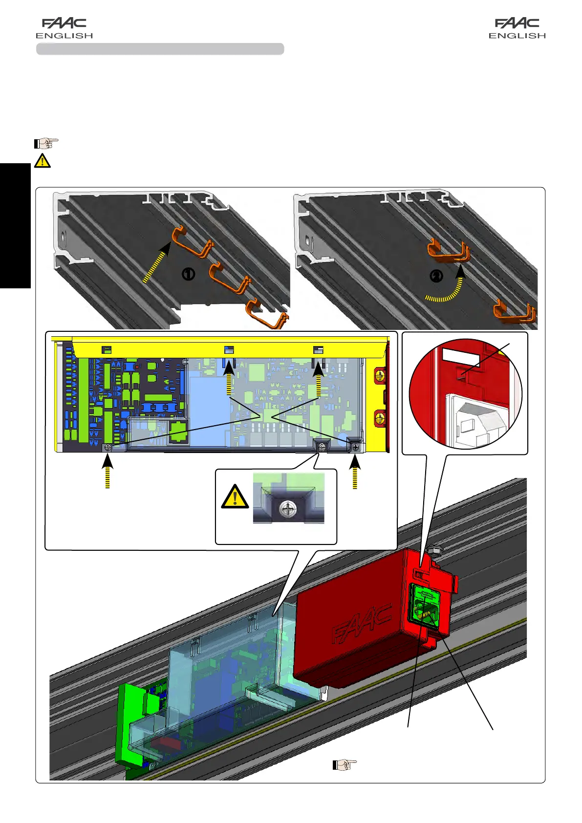
• Connectthe115V~/230V~powerpluginthespecificconnectorofthepowersupplyunit(Fig.44ref.c).
•
To remove the electronic board cover, unscrew the two screws and press the two clips (Fig. 44 ref. )
Check if the switch in fig. 44 ref.d is correctly positioned (230V~/115V~).
• Checktheefficiencyofallinstalledaccessories,especiallyphotocellsandsensors.
Fuse
5x20 T2,5A/250V~
fig. 44
A spare fuse is supplied
.
Attention: do not remove
the highlighted screw
e
 Loading...