27
b
A
a
c
B
A
B
a
a
a
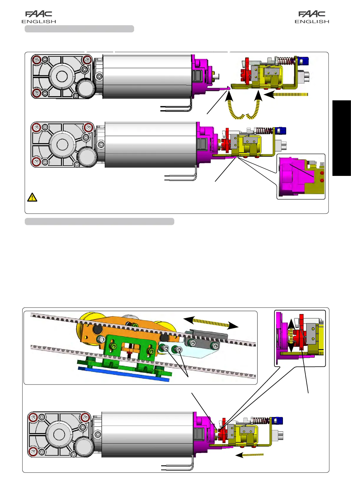
15A FITTING THE MOTOR LOCK
WerecommendyouperformtheelectricalconnectionofthemotorlocktotheE140boardbeforefittingitonthemotor.
Consulttheseinstructionsinthesectionconcerningthecontrolboardconnectionsinordertoperformthewiring.
Fitthemotorlockinsertingthemotorpinintotheslotofthemotorblockasshowninfigure45ref.AeB
Important:Noteforthemotorlockdisassembly
Payattentionwhenworkingonthemotorretainingtoothinordertoavoidbreakages:leverwithaflat-tip
screwdriverbetweenretainingtoothandmotorlockfig.45Ref.a
fig. 46
fig. 45
Themotorlockingdeviceguaranteesthattheleavesarelocked
when closed. If requested when ordering, the motor locking
device is supplied pre-installed on the support profile of the
automated system and includes the knob operated internal
releasesystem.
Adjustmentprocedureforthemotorlockingdevice:
• Closetheleaves.
• Manuallypushthelever(fig.46ref.a)towardthemotorshaft,
checkingcorrectcouplingasshowninfig.46,ref.A).
• Movethelever(fig.46ref.b)verticallyandlookforanyplay
betweenthemotorshaftandmotorlockcoupling.
Ifthereisnoplay,proceedasfollows:
•Loosenthetwoscrews(fig.46refB
c)whichconnectthebeltfit-
tingtothedrivecarriage(onbothcarriagesfordoubleleaves).
•Gentlymovethebeltcouplinghorizontally,untilthelevermoves
freely;tightenthescrewsyouhadloosened.
.
15.1A ADJUSTING THE MOTOR LOCK
 Loading...