28
a
b
c
a
b
d
f
h
b
c
b
c
h
c
b
a
c
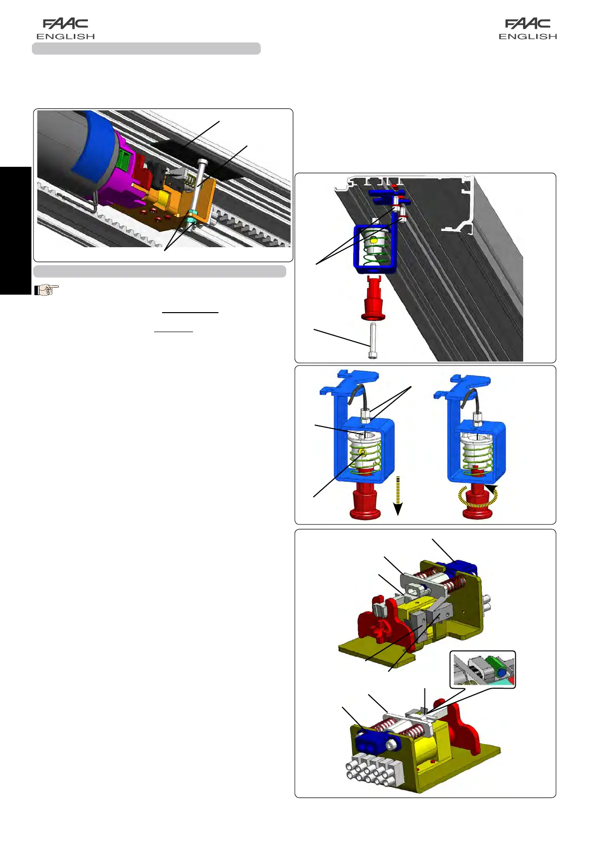
16A INSTALLING THE INTERNAL RELEASE KNOB
DOUBLE LEAF APPLICATIONS:
For Vp = (800 ÷ 1000) mm, we advise you to install
the release knob on the side opposite the motor.
For Vp = (1000 ÷ 3000) mm, we advise you to install
the release knob on the same side as the motor.
• Assemblethereleaseknobonthesidebracketasshownin
fig.47,afterhavinginsertedthetwoplatesintheprofile(fig.
47ref.a)
• Screwtheadjustingscrewwiththerelevantsecuringnutas
showninfig.48ref.a.
• Withdrawapprox20cmofsteelcablefromthesheath.
• Insertthesteelcableintotheadjustingscrew;letitrouteinside
thereleasedevice(fig.48ref.b).
• Blockthesteelcablebymeansoftherelevantclampand
tightenthescrew(fig.48ref.c).
• Take the black sheath of the cable against the adjusting
screw
• Tightentheadjustingscrewonthebracket.
• Blocktheknobbypullingitandturningitby90°andmake
surethatitdoesnotreturntoitsoriginalposition(fig.48).
• Route the cable with sheath inside the cable channels till
reaching the motor lock taking care to avoid too narrow
curvesofthesheath.
• Approachthecablewithsheathtopartboffig.49andcut
thesheathinexcess.
• Routethecable(fig.49b)insidepartatakingthesheath
to end.
• Insertthecableintheclamp(fig.49ref.c).
• Pulltheparthtoitsend(bycompressingthesprings)and
screwtheclampscrewcthusblockingthesteelcable.
• Cutthesteelcableinexcess.
• Checkifthemotorlockcouplingisfreefromthemotorshaft
coupling(fig.46ref.A).
• Ifadjustingoperationsarenecessary,usetheknobbracket
adjustingscrew(fig.48ref.a).
• Releasetheknobbyturningit90°andcheckiftherelease
deviceoperates.Makesurethat,bypullingtheknob,thedoor
openingmicroswitchactivates(fig.49refd).
Consulttheseinstructionsinthesectionconcerningthecontrol
boardtoperformtheelectricalconnectionofthemotorlock.
If an external release device must be fitted, use the relevant
key-operatedpush-buttons.Insertthereleasecableonthemotor
lockusingtherelevantseat.
The version A140 AIR H140 is supplied with the release knob
havingaheightoverH140.Tofitandadjustit,followthesame
instructionsprovidedfortheversionA140AIRH100.
fig. 48
fig.49
fig. 47
15-2A MOTOR BLOCK BRACKET ADJUSTMENT
Anadjustmentscrewisusedtosettheheightofthemotorblockbracket.
Applyanadhesivestripontheupperpartoftheprofile,asshowninthefigure46brif.a.Fitthescrewontheendsectionof
theendbracketofthemotorblockwiththeheadfacingupwardsandrestingonthestrip,asshowninthefigure46brif.b.
Thenmaketheadjustmentviathe2nutsontheendpartofthescrewrefertothefigure46brif.c
fig. 46b
 Loading...