29
a
x2
a
b
c
18A MICROSWITCH FOR SUPERVISION OF MOTOR LOCKING DEVICE
Thisaccessory makesitpossible toverify correct operation of
themotorlockand,ifitstayslockedwhileopen,signalsanerror
viathecontrolboard.
InstallthesupervisionmicroswitchasshowninFig.49ref.f. For
electrical connection and programming, refer to the control
board/accessoriessectionoftheseinstructions.
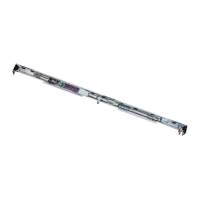
19A SUPERVISION SENSOR
The supervision sensor is an accessory (magnetic sensor) to
whicharelaycanbeconnectedviaaconnector,inorderto
haveadoorclosed/doornotclosedstate(e.g.toconnectan
alarmsystem).
Sensorinstallationprocedure:
• Screw the magnet on the carriage nearest to the closing
contact point, using the threaded hole on the belt fitting
(fig.51ref.a).
• Assemble the sensor to the bracket (fig. 51 ref.b), using
theplasticnuts.Insetathreadedplateontheseatsofthe
supportprofile,andinstallthebracket,usingthescrews(fig.
51ref.c).Checkifthesensorisinlinewiththemagnetwhen
theleafisclosed.
17A INSTALLING THE CLOSING HOUSING
Cut the housing profile to the same length as the
support profile, except for 2mm to facilitate closing
housing blocking with side panels.
Ifthemotorlock,andrelevantreleaseknobarepresent,drilla
holeofatleast18mmtakingcaretocentretheholewiththe
releaseknob.
Tofacilitatethehole,usethelineinfig.50ref.aasareference.
if the release knob is present, to open the housing,
dismantle the knob, unfastening the screw in fig.47
ref. b
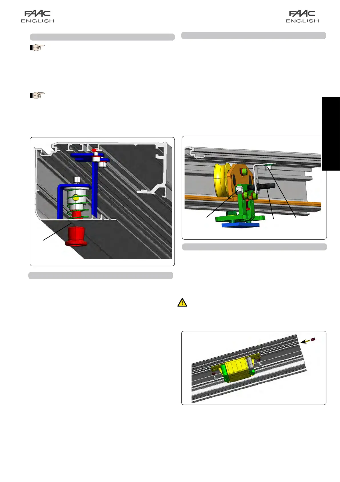
20A INSTALLING THE EMERGENCY BATTERY KIT
• FittwoplatesinthesupportprofileasshowninFig.52.
• Securethebatterysupportonthesupportprofile,usingthe
twosuppliedscrews.
• For electrical connection of the battery board and for
programming, refer to the control board section of these
instructions.
Important:Afterhavingfittedthebatterykit,enableitfrom
theE140boardinordertomakeitoperating:tothisend
usepush-buttonsF+/-onparameterbAortheSDKeeper
programmingunit.
fig. 50
fig. 52
fig. 51
 Loading...