31
200
200
30
37,5
30
30
B
A
55
117
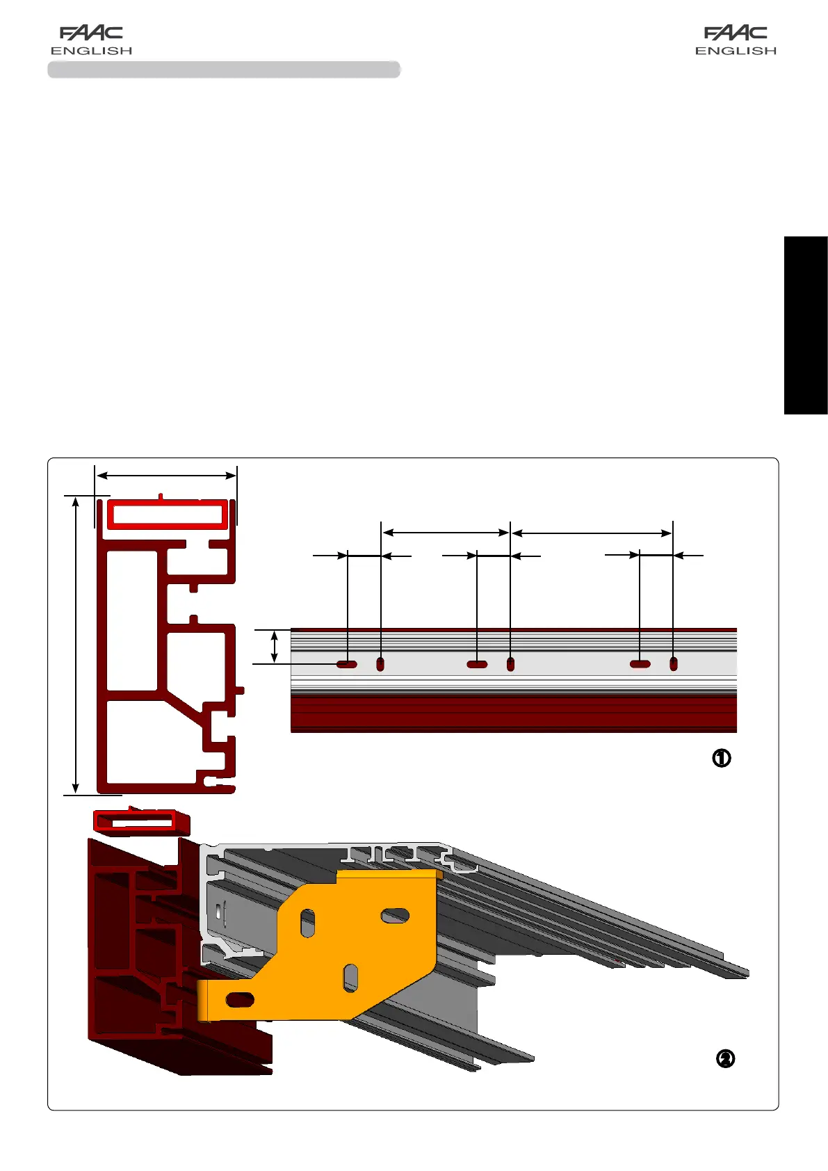
fig. 54
21 A140 AIR H100-H140 FREE-STANDING KIT
A140AIRFree-standingconsistsofasupportprofileandofanother
profilewhichgrantsthefree-standingfeature.
The cross beam can be secured to both ends using the “Side
fasteningbracketkit”.
Thefree-standingprofile,whenfixedtotheends,isguaranteedup
toamaximumlengthof3000mm;forgreaterlengthsthecross
beamneedstobesecuredalsoinintermediatepositionsusing
thetie-rodsintherelevantslots.
Itisusedwhenthecrossbeamcannotbecompletelysecuredto
abearingstructureorwhenthesurfaceisnoteven.
Free-standing profile – fastening with side brackets
The cross beam of the automated system with the
free-standingprofilecanbesecuredtobothendsbyusing
thesidebracketsaccessory.fig.54.
•Determinetheexactpositionofthecrossbeamtakinginto
considerationtheoveralldimensionsindicatedinfig.54.
•Assemble the support profile to the free-standing profile
byinsertingtherelevanttie-rods,thenscrewthenutswithout
tighteningthem.
Secure the side plates on the cross beam in the following
way:
•Positiontheplatesintherelevantseatsandsecuretheside
platesusingthethreefasteningscrewsM8.fig.55
•Lockthetie-rodsintherelevantseatsusingtheirnuts.
•Fix the side plates using suitable dowels (not
standard-supplied)
According to the length of the cross beam, intermediate
fastening points can be necessary (on wall or on ceiling
accordingtothecase):
from3000to4000mmacentralfasteningisrequired.
from 4000 to 6100 mm two intermediate fastening points
arerequired.
Acentralfasteningisinanycaserecommendedalsofora
lengthbelow3000mm.
Free-standing profile – wall-mounted
•Drillaseriesofholesonthefree-standingprofileintheposition
indicatedinfig.54atadistance of approx.200mm between
eachother.
•Determinetheexactpositionofthefree-standingprofiletaking
intoconsiderationtheoveralldimensionsoffig.54a.
Thecrossbeammustbesecuredparalleltothefloor.
•Securethefree-standingcrossbeamtooneend.
Liftthecrossbeamandlevelitparalleltothefloor.
Securetheotherend.
Securecentrallybyliftingthecrossbeamwithstrengthinorder
toalignthethreefasteningpointsfig.54.
 Loading...