3
B614 11 532297 - Rev.D
tttttt
tttttt
tttt tttt
tttttt
tttt
tt
tttttt
tttttt
tttttt
BARRIER B614 110-120 VAC
FAAC International
xxxxxxxx xxxxxxxxxxx xxxxxxxxxxxx
xxxxxxxxx
0118 0001
Part Number
Product name
IDENTIFICATION NUMBER
Month/year of production +
progressive number for the
month of production
Example:
made in:
January 2019
progressive:
0001
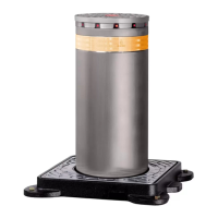
2.6 PRODUCT IDENTIFICATION
The product is identified by the plate (3).
2.7 TECHNICAL SPECIFICATIONS
The B614 is an electromechanical barrier with a E614
electronic board built in. The B614 must be installed
on the specific foundation plate and set onto a plinth.
RH/LH barrier The B614 can be easily installed as a right
hand or left hand barrier without having to do any
major modification the its structure.
It's reccomended to install the barrier with the door
towards the inside of the property for easier access.
The barrier is defined by looking at it from the door side:
- RH barrier (right): the arm closes towards the right
(in a clockwise direction)
- LH barrier (left): the arm closes towards the left (in
an counterclockwise direction)
Self-Locking gear reduction To allow manual operation,
use the provided release mechanism.
Encoder The B614 has a built in encoder. The encoder
constantly detects the precise position of the arm and
makes it possible to manage the end of movement and
slow downs stored with the set up.
Anticrushing operation The encoder allows the board to
implement an anticrushing feature:
- the detection of an obstacle during closing causes
the movement to be reversed
- the detection of an obstacle during opening causes
the arm to stop.
Adjustable positive stop The barrier has built in adjustable
mechanical positive stops to set the end of opening
and closing movements.
Equipment A rectangular arm can be installed. The
components necessary for the installation and the op-
tional equipment are listed in the dedicated sections.
Balancing system One or two balancing springs must be
used to balance the arm. The use of single or double
springs depends on the length and configuration of
the installed arm.
!
The balancing system is important for safety reasons
to ensure the stability and control of the arm during
movement and keep it operating properly over time.
Master-Slave Configuration The configuration of two bar-
riers that open in opposite directions can be achieved
with the Master-Slave configuration.
Power supply voltage 115V~ +/-10% 50/60 Hz
Electric motor 24 V
"
Max power 165 W
Max torque 220 lbf (300 Nm)
Opening time (80°)
- arm < 9.8 ft (3 m)
- arm > 9.8 ft (3 m)
less than 2 sec.
less than 3 sec.
Use frequency Continuous use
Ambient operating tem-
perature
-4 ° to +131 °F (-20 ° to +55 °C)
Protection rating IP 55 (control board) - IP 44
Dimensions (L x D x H) 9.75 x 14 x 45.75 in
(247 x 357 x 1163 mm)
Weight 88 lb (40 kg)
FAAC foundation plate
Dimensions (L x H) 9.05x12.01 in (230 x 305 mm)
FAAC arm Arm length
Rectangular arm 4.4 ... 12.5 ft (1.35 ... 3.81 m)
3 Technical data