4.1 Technical data of control unit
Operating voltage 230V AC +/-10%, 50/60 Hz
Relay contact 1 relays3
max. switching current x A AC1 - 250V AC11 10
x 1 A AC1 - 250V AC2 6
max. switching voltage 250V AC - 50..60 Hz
Display 4 13 mm LED-Display, digits
Display range -999 ... 9999
LED switching status displays 3 mm
Number of sensor inputs 1 or 2
Measurement range -5° ... +95°C
Temperature resolution 0.1°C
Sensor input KTY 81-210
Control mode two-step controller
Hysteresis* 0.1 K .. 99,9 K (standard adjusting 0.7 K)
Water detection via 2 independent level monitors
Target temperature T1* standard adjusting °C4
Target temperature T2* standard adjusting 4°C
Digital inputs 8 (via optocoupler)
Interface 2x RS 485
Connection Plug-in screw connections
for cables up to 2 5 mm².
Environment specifications:
- Operation temperature 0° .. +50°C
- Storage temperature -20° .. +70°C
- max. humidity 75% (no dew)
Technical data subject to change
Page 9
4. Technical Data
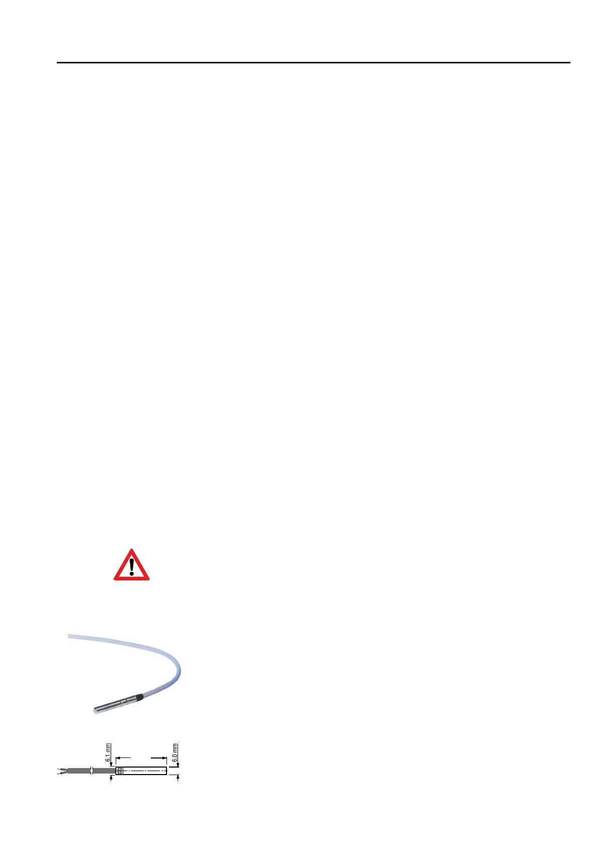
4.2 Fitting the sensor
When setting the temperature controller parameters (and whenever the sensor is
replaced) the “actual value correction” [Parameter C91] must be adjusted so that the
temperature measured corresponds to that shown on the display. A reference thermo-
meter should be used for this purpose.
Pay attention to the permitted temperture range for sensor cable exposure.
40 mm
The sensor cable must not be chafed or kinked.
There must be no substantial mechanical pressure on the sensor tube.
Do not place the sensor and the high-voltage cable in the same cable
conduit (not even within the switchbox).
Temperature range sensor cable -10°C .. +70°C
Changing the sensor cable length
lf it is necessary to shorten or lengthen the sensor cable on installation (or if a sensor
other than the one supplied is to be fitted), the "actual value correction" parameter
must be adjusted accordingly.