> > > > 31
8.1.7 Pilot/thermocouple assembly
1) Remove the burner tray (see 8.1.3).
2) Remove the lead from the pilot spark electrode.
3) Break the gas pipe connection to the pilot.
4) Unscrew thermocouple nut from the rear of the gas control.
5) Unscrew pilot assembly from the burner tray (2 screws).
6) Replace and re-assemble in reverse order
8.1.8 Burner and injector
1) Remove the burner tray (see 8.1.3).
2) Remove the lead from the pilot spark electrode.
3) Break the gas pipe connection to the pilot.
4) Unscrew thermocouple nut from the rear of the gas control.
5) Unscrew pilot assembly from the burner tray (2 screws).
6) Replace and re-assemble in reverse order.
A. Thermocouple
B. Spark electrode
C. Pilot hood
Fig. 27: Thermo couple assembly
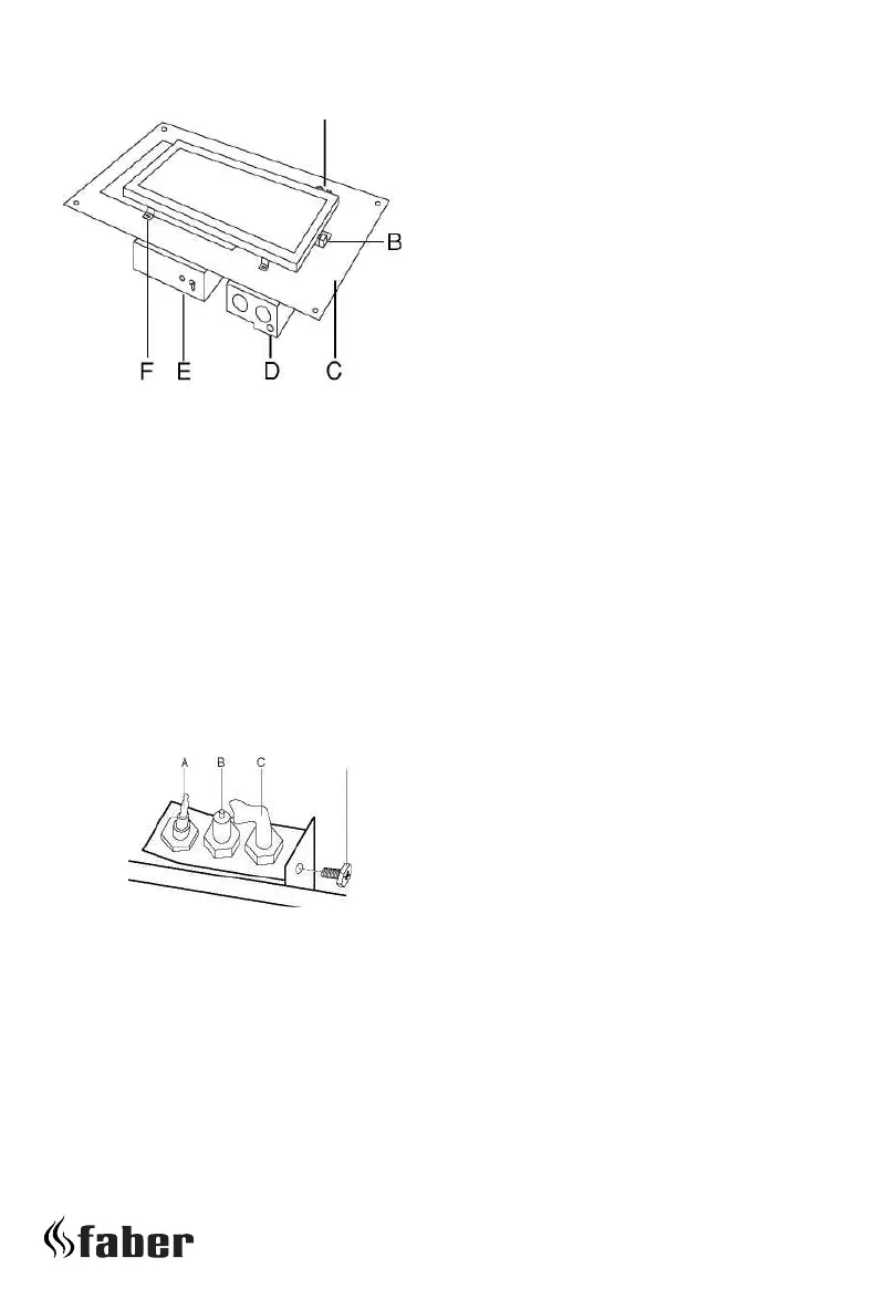
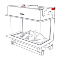
Fig. 26: Burner tray assembly Flat Fibre Burner
A. The pilot and flame sensing
B. Injector (Spectra at burner inlet)
C. Burner tray
D. Gas control
E. Receiver remote control
F. F i x i n g b r a c k e t