FX15 Controller Technical Bulletin
C A B - Bt
1 2
3
AGND
AI1
EXT V
4
5
AGND
AI2
6
7
AGND
AI3
8
EXT V
HT-9001-UDx
Active Humidity and Temperature Sensor
FX16
-
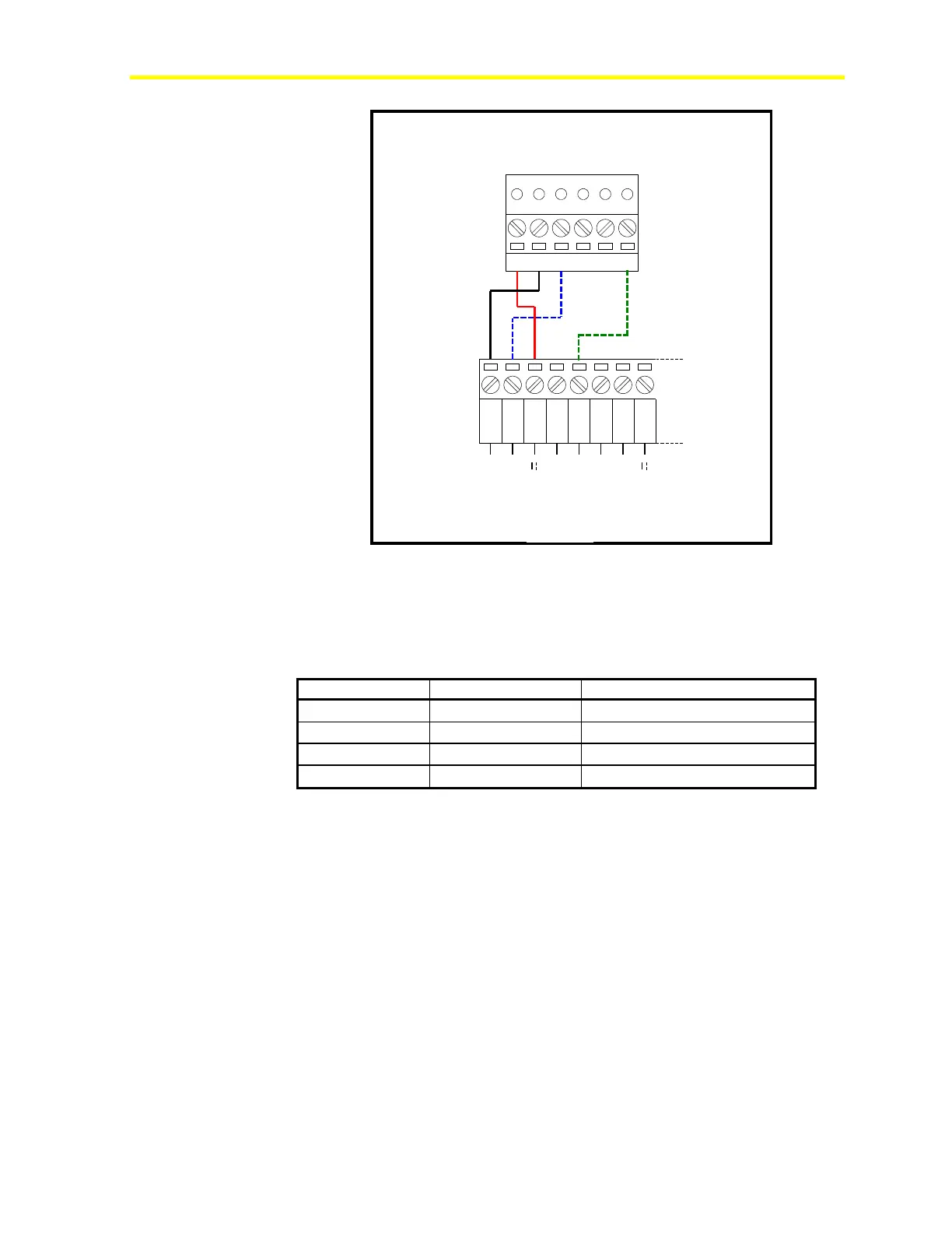
Figure 32: Active 0-10 V Probe, Connection Diagram
The inputs must be configured to accept 0-10 V signals by the
application software in the FX15 controller. The AI Jumpers must be
opened (factory default setting) to accept voltage inputs.
Table 4: Active 0-10 V Sensors
C Sensor Power Supply 16 V, 80 mA
Temperature Output 0-10 V
Note: The numbers inside the parentheses are the FX15 controller
terminal numbers.