FX16 Master Controller Technical Bulletin
10
Isolation Diagram
1
41 51 91787255 62 75
9
21 26 31
2
42 52 92797356 63 76
10
22 27 32
3
43 53 93807457 777154 61
11
23 28 33
4
44
12
24 29 34
5
45
13
25 30 35
6
46
147
47
158
48
Digital Inputs
nalog Input
Extension
Bus
To Remote
Display
Digital Outputs Analog Outputs Power Supply
TB1
TB9
()
*
TB8TB7TB6TB5TB4TB3
J2
J1
To
Supervisor
To
Modem
TB2
()
*
()
**
()
***
()
**
()
**
()
**
CPU
FX16-005_10 2003
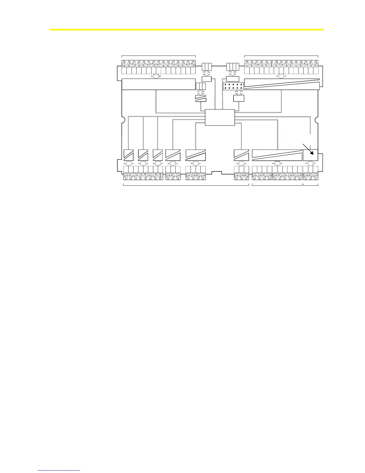
Figure 4: FX16 Isolation Diagram
Figure 4 displays the isolation diagram for the FX16 controller. Use the
following list as a reference to understand the diagram:
• (*) Opto-isolated from the Central Processing Unit (CPU) circuits
(max. 500 V):
LP-FX16D and LP-FX16X (not Rev. A), when separate power
supply is used
LP-FX16X (Rev. A), with same power supply as controller
• (**) Not isolated from CPU (Analog Inputs, Local Link Extension
Bus, and Modem connections)
• (***) DC/DC converter with dielectric strength up to 500 V
• (****)
Isolation of power supply from CPU is hardware model
dependent:
− Models LP-FX16D and LP-FX16X (not Rev. A) are not
isolated.
− Model LP-FX16X (Rev. A) is isolated (maximum 500 V).
FX16D and FX16 Controllers (Not Rev. A)
Consider the following information when you work with the
connections details for FX16D and FX16X controllers (not Rev. A):
• Analog Inputs (AIs) are not isolated from the processor circuits
(CPU) or the 24 VAC power supply.
(****)