FX16 Master Controller Technical Bulletin
12
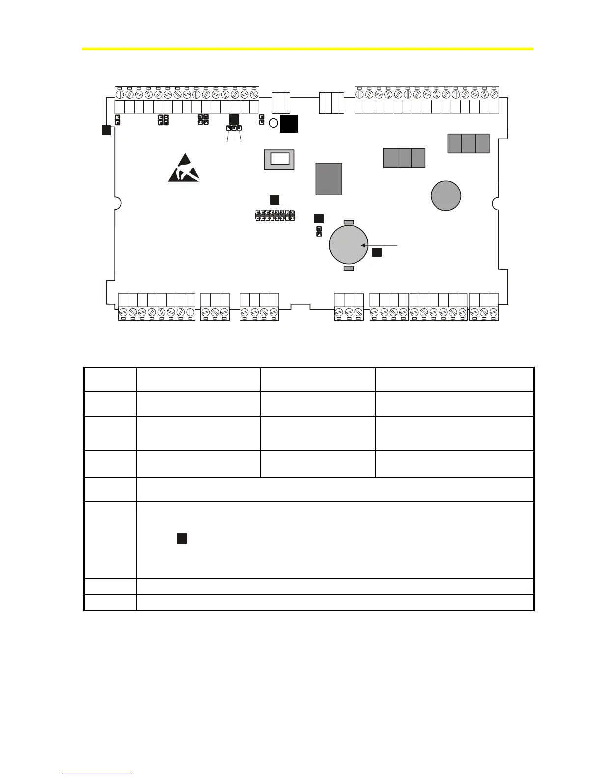
Jumper Details
e
d
c
a
b
Battery
AI1 AI2
AI3
AI4 AI5
AI6
1 2 3
FX16-004
10 2003
Figure 5: Jumper Connections
Table 1: Jumper Connections
Diagram
Location
Analog Input 0-20/4-20 mA Resistive, 0-10 V or Ratiometric
a
AI1-AI6 Jumpers Closed Jumpers Open
(Default configuration)
Sensors Power Supply Audio Visual
Presentation Series
(AVPS) +5 V 20mA
EXT VDC+16 V 80mA (Total)
b
Terminal Number 13 Pins closed between 1 and
2
Pins closed between 2 and 3
(Default configuration)
c
Battery Type CR2032, average life time: 3 years, dispose of correctly with due regard for the
environment
d
Pin strip closed: battery backup enabled
Pin strip open: battery disconnected (to preserve charge)
Jumper
d
is set to ON at the factory and should only be set to OFF if the controllers are to be kept
in storage without power for an extended period of time. The jumper must be set to ON before the
controllers is installed and powered up, otherwise backup function for RAM and Real-Time Clock
(RTC) is not enabled.
e
Plug-in connector for optional cards insertion
f
Hole for standoff for communication card