FX16 Master Controller Technical Bulletin
50
Connecting Passive Resistive Sensors
The analog inputs in the FX16 Master Controller accept linear resistive
signals as Resistive 2k ohm configuration. The Analog Input software
can also linearize signals provided by the most common sensors such as
Ni1000, Pt1000 (HT-9006), NTC 2k2 (RS-1143), NTC 10k (TM2141),
and A99 (A99BB).
You must configure the inputs to accept the appropriate resistive sensor
by the application software resident in the FX16 Master Controller. You
must also open the AI Jumpers to accept resistance input (factory
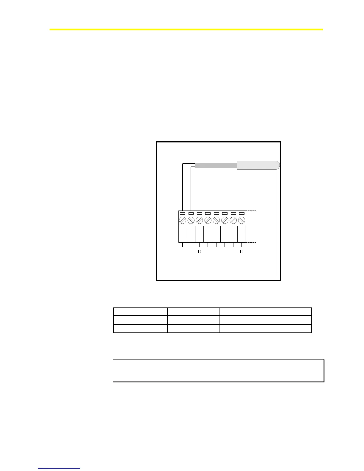
default setting). Figure 44 shows an A99 wiring diagram. You can
connect any resistive sensor the same way.
1 2 3
AGND
AI1
EXT V
4 5
AGND
AI2
6 7
AGND
AI3
8
EXT V
FX16
A99BB
Resistive Temperature Sensor
Figure 44: A99 Resistive Sensor Connection Diagram
Table 14: Passive Resistive Sensors
FX16 Terminals A99 Wires Description
AI Com (1)
Any wire Common Reference
AI1 (2)
Other wire Temperature Signal
Note: The numbers between the brackets are the FX16 terminal
numbers.
IMPORTANT: The two resistive sensor leads are the same, in that they have
no polarity; therefore it is not necessary to respect any specific order when
connecting to the terminal block.