Do you have a question about the FADAL VMC 3020 and is the answer not in the manual?
Key safety guidelines and warnings for machine operation, ensuring user and equipment protection.
Guidelines for handling sensitive electronic components to prevent damage from static discharge.
Comprehensive list of safety precautions for operation, maintenance, and work area environment.
Procedures for powering on the machine and performing essential pre-operation checks.
Steps to establish the machine's home or reference position, crucial for accurate operation.
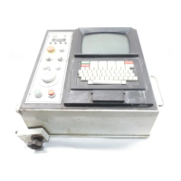
Overview of the pendant control panel, including button functions and layout for machine interaction.
Detailed description of the hard keys on the machine's main control panel and their functions.
How to operate the machine using manual data input in automatic mode.
Explanation of different jogging methods for precise axis control and positioning.
Using MPG or JOG keys for precise incremental axis movement.
Methods for moving the tool quickly or incrementally using jog and rapid jog controls.
Procedure for manually inserting and removing tool holders from the spindle.
Process for loading tools into the spindle from the Automatic Tool Changer.
Setting the spindle speed and direction for operation.
Manual control of spindle rotation using dedicated buttons.
Understanding the difference and relationship between Machine Coordinate System (MCS) and Work Coordinate System (WCS).
Defining the machine's home position relative to Machine Zero.
Setting fixture offsets (e.g., ZO1-ZO8) for workpiece referencing.
Defining offsets for tool length, diameter, and wear.
Procedure to set base and zero offsets using measurement functions like edge, corner, or hole.
Methods for setting tool length and diameter offsets using manual or automatic probe measurements.
Manually setting base and zero offsets via the dedicated soft key interface.
Accessing and editing the tool list for managing tool offsets and parameters.
Manually setting the length of a tool using a gauge block or reference.
Entering tool diameter values into the tool list for accurate machining.
Adjusting tool length or diameter by incremental wear values.
Displays user-defined R parameters that can be activated by the program.
Using buttons to turn flood and mist coolant on/off.
Steps to create a new CNC program for automatic execution.
Procedure for modifying existing CNC programs.
Selecting and activating a program for automatic operation.
Executing the active program in automatic mode.
Starting program execution from any block within the code.
Safe steps to turn off the machine's power supply without loss of memory.
Procedure to reset and resume operation after an emergency stop activation.
Moving the tool changer bucket up or down.
Activating the tool changer arm to move forward.
Activating the tool changer arm to move backwards.
| Controller Type | CNC |
|---|---|
| Axis Configuration | 3-axis |
| Tool Capacity | 21 tools |
| Programmable Feed Rate | 0.1-400 IPM |
| Control | Fadal CNC 88HS |
| Display | CRT or LCD |
| Resolution | 0.0001 inch |
| Axis Control | 3-Axis Simultaneous |