Auxiliary modules
204
4.
AUXILIARY MODULES
External Ballast resistors
194
DDS
HARDWARE
Ref.1310
Chapter 8. INSTALLATION shows the installation rules for external brak-
ing resistors that must be followed strictly in order to install them properly.
Chapter
11. DIMENSIONS of this manual shows their dimensions.
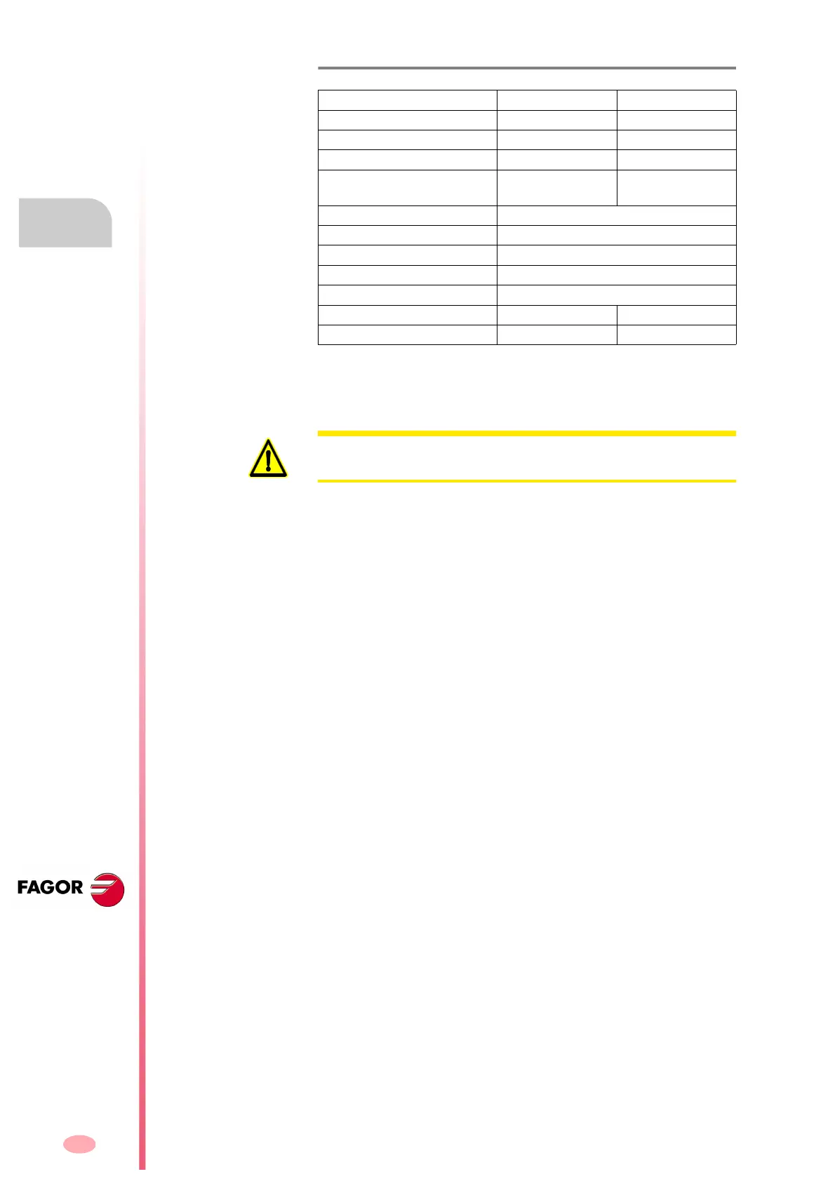
T. H4/6 External Ballast resistor with internal thermostat. Technical data.
With internal thermostat ER+TH-18/1800 ER+TH-18/2200
Resistor 18 18
Tolerance ± 5% ± 5%
RMS power 1300 W 2000 W
Energy absorbed in 5"
overloaded
55 kJ 83 kJ
Operating room temperature 5 °C to 45 °C (41 °F to 113 °F)
Storage temperature - 20 °C to 60 °C (- 4 °F to 140 °F)
Relative humidity < 90 % non condensing at 45 °C (113 °F)
Operating vibration 0.5 G
Shipping vibration 2 G
Sealing IP 54 IP 54
Approx. mass kg/lb 3.0 / 6.61 7.0 / 15.43
Note that the value for the rms power depends on the following conditions:
Resistor installed vertically with the connection cables at the bottom and
separated from the nearest surface at a distance of at least 10 cm (about 4
inches).
WARNING. Careful with the surface of these resistors. Remember that its
temperature may reach 410 °C (770 °F).