Auxiliary modules
AUXILIARY MODULES
Auxiliary power supply
4.
201
DDS
HARDWARE
Ref.1310
NOTE. See chapter 13. COMPATIBILITY for the references of the com-
patible APS-24 power supplies with the XPS or RPS power supplies in
case it is installed.
Block diagram
INFORMATION.
In case of micro-surges or total mains power outage, this
module guarantees the stability of the 24 V DC to feed the control circuits of
the drive modules connected to the bus and maintain it for as long as the
emergency stop of the motors lasts, thus stopping the axes in a controlled
manner.
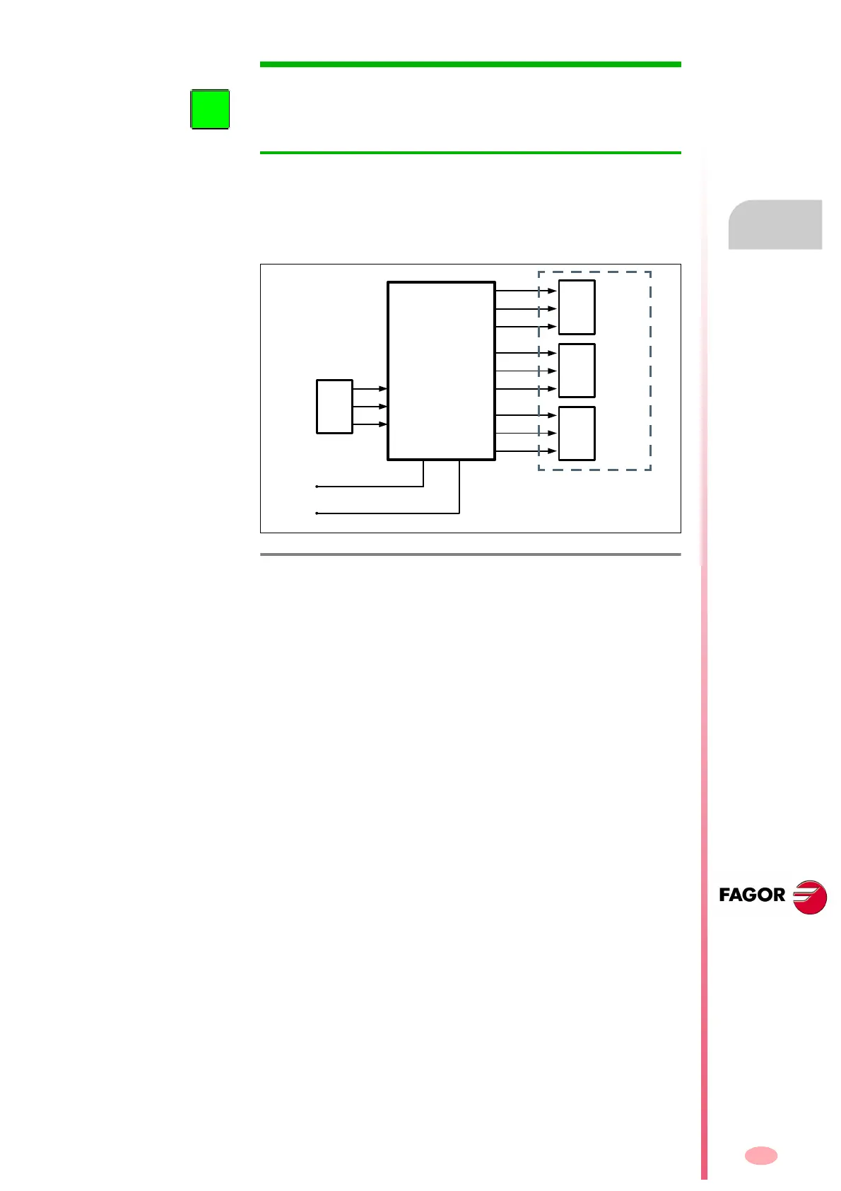
F. H4/9
Block diagram of the auxiliary power supply APS-24.
X1
POWER
SUPPLY
L1
L2
CHASSIS
L+
L-
X2
+24VDC
0VDC
CHASSIS
X3
+24VDC
0VDC
CHASSIS
X4
+24VDC
0VDC
CHASSIS
Imax total = 10 A
Pmax total = 240 W