Auxiliary modules
204
4.
AUXILIARY MODULES
Auxiliary power supply
202
DDS
HARDWARE
Ref.1310
Connectors
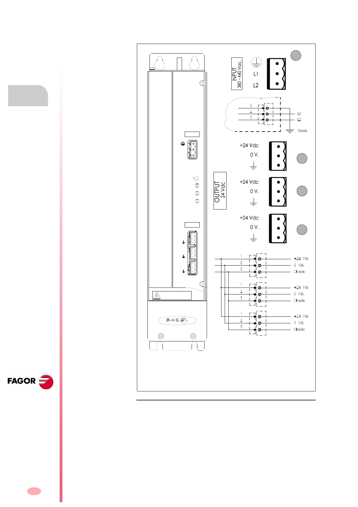
The auxiliary power supply APS-24 has the following connectors:
F. H4/10
Connectors of the APS-24 power supply.
X1. Input connector to feed the auxiliary power supply from mains. It ad-
mits a voltage between 400 V AC and 460 V AC.
X2. Output connector of the auxiliary power supply offering 24 V DC.
X3. Output connector of the auxiliary power supply offering 24 V DC.
X4. Output connector of the auxiliary power supply offering 24 V DC.
X1
X2
X3
X4
Note. The maximum current of 10 A is the total current that the power sup-
ply can provide as the sum of all the currents that may be supplied through
the three 24 V DC connectors; in other words, it can provide a maximum
total power of 240 W (all of them together), but not through each one.
Imax total = 10 A
Pmax total = 240 W
DANGER
HIGH VOLTAGE
DISCHARGE TIME > 4 Min
L2
L1
X1
+24Vdc.
0V.
+24Vdc.
0V.
+24Vdc.
0V.
X2
X3
X4
INPUT
380-460 Vac.
OUTPUT
24 Vdc.
RESET
OVER VOLTAGE
OVER CURRENT
ON
APS 24