ALYA INSTALLATION AND USER’S MANUAL - EN
Edition 2.0 Sept 2018 Pag. 14 di 32
G. Calculate the proper length of the column (14), according to the formula
L=H-DHC-1020 mm.
Cut the exceeding column (14) part on the side were NO LATERAL BORES
ARE PRESENT
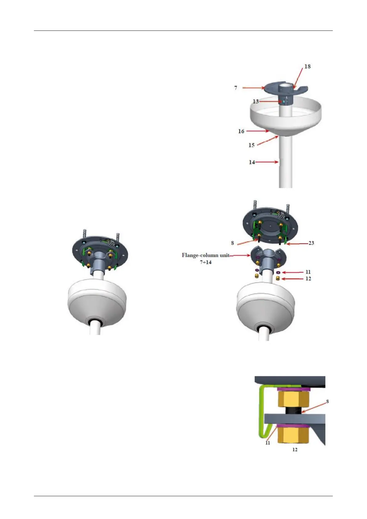
H. Insert them column (14) in the flange (7) and mark on the column (14) the
position of the bores on the flange (7). Pay attention the orientation of the column
in relation to the dental unit. Remove the column and carry out two Ø 8 bores at
the marked points.
I. Fit on the column (14) the ring(15) at about 300mm height (it is only temporary
position to allow the assembling)
J. Insert the ceiling light support (16) on the column (14)
K. Fit the column (14) in the special bore of the column fixing flange (7)
L. Lock the screw (13) and the two screws (18) with hexagonal spanners
(installation accessory). Tighten sturdily the screw (13) and make sure the screws
(18) have passed through the bores on the column (14)
M. Hook the unit freshly assembled (column fixing flange
(7) + column (14) ) to the fixing guides (23), by matching
the 4 bores of the flange (7) to the screws (8) of the flanged
on the ceiling (1)
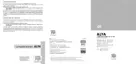
N. Screw (without locking) the nuts (12) and the remaining washers (11) on the screws (8) of
the ceiling flange (1)
O. Unscrew the three screws (19) of the column (14) and remove the bushing (20)
P. Insert the bushing (20) on the lamp pin (21)
Q. Insert in the pin (21) groove the key switch (22)