44
NISEA
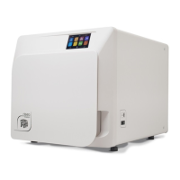
2 EQUIPMENT DESCRIPTION
Fig. 2 and Fig. 3
20. Data plate
Fig. 1
1. Touch screen display
2.Bio-xlter
3. Motorised closure screw
4. USB port
5. Main switch
6.Feedtankllingconnection
7. Discharge tank draining
connection
8. Feed tank draining connection
9. Manual feed tank emergency
llingconnection
10. Nut screw for motorised
closure
11. Porthole
19.Dustlter*
21. Tray holder symbol
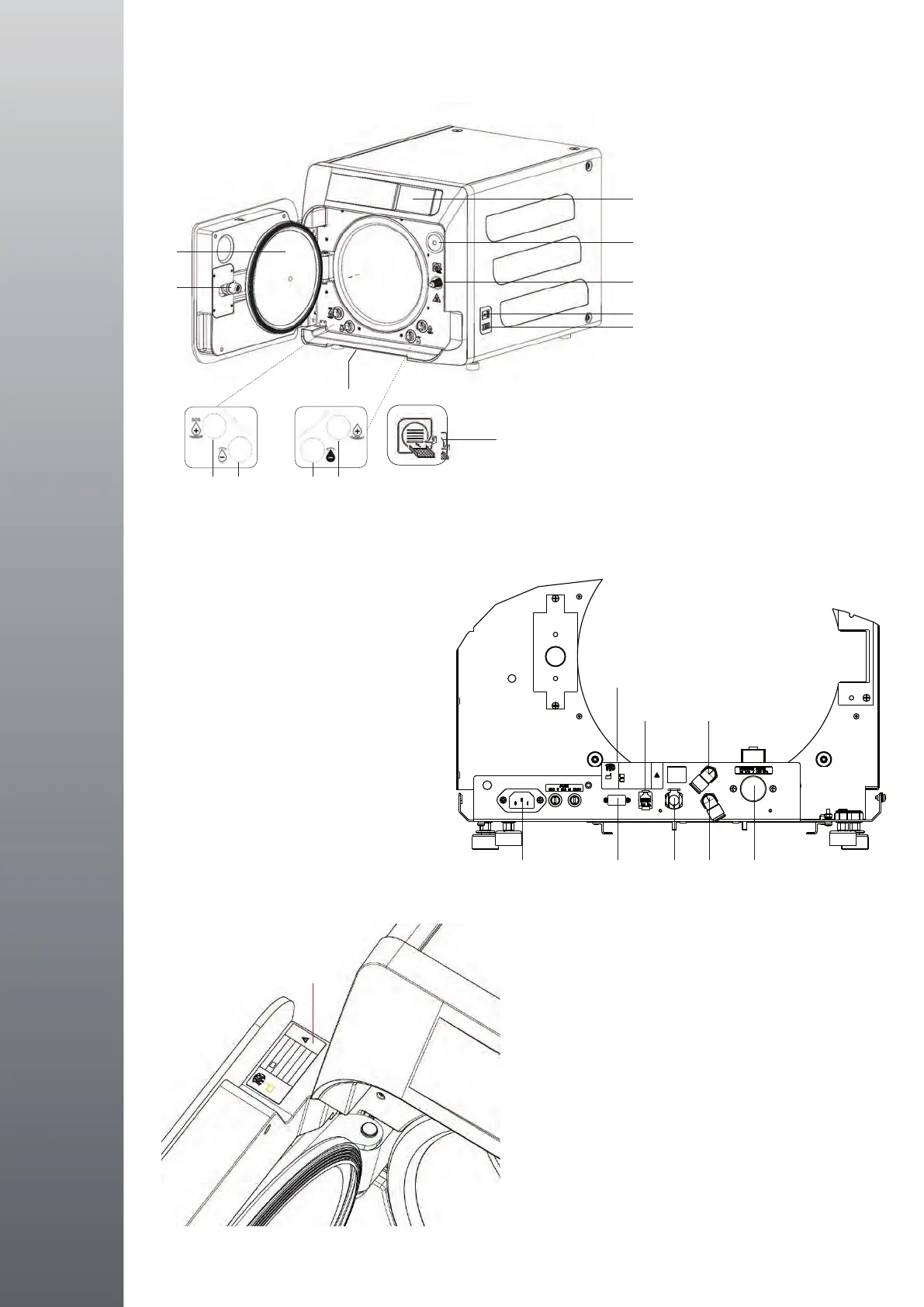
Fig. 2 – Rear view
12. Power supply
13. RS-232 port for external printer
14. LAN port *
15. Discharge tank drain connection for
main drain system *
16. Discharge tank vent
17. Feed tank vent
18.Solenoidvalveforllingthefeed
tank from the mains water supply *
(Allowable pressure from
20 kPa to 250 kPa)
* For the Premium version only
VEDI Fig. 1
1. Display touch screen
2. Filtro bio-x
3. Vite chiusura motorizzata
4. Porta Usb
5. Interruttore
6. Innesto per carico serbatoio di carico
7. Innesto per scarico serbatoio di scarico
8. Innesto per scarico serbatoio di carico
9. Innesto per carico di emergenza serbatoio di carico
10. Madre vite chiusura motorizzata
11. Oblò
19. Filtro anti-polvere *
VEDI Fig. 2 – Vista posteriore
12. Alimentazione
13. Porta RS-232 per stampante esterna
14. Porta LAN *
15. Innesto per scarico serbatoio di scarico da rete idrica *
16. Sfiato serbatoio di carico
17. Sfiato serbatoio di scarico
20
11
10
1
2
3
4
5
19
9 8 7 6
21
12 13 15 17 18
20
14 16
 Loading...