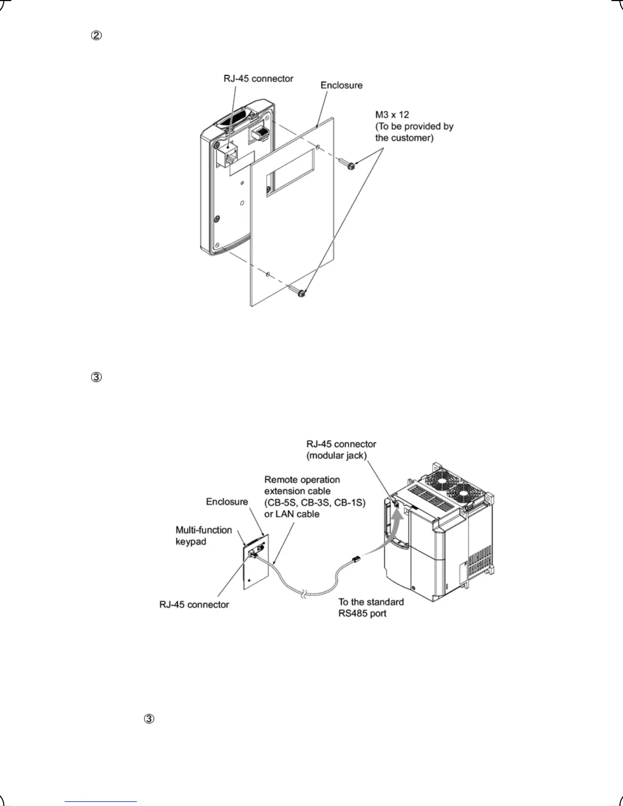
Mount the multi-function keypad onto the enclosure with 2 screws as shown in Figure 2.8. (Recommended
tightening torque: 0.7 N•m)
Figure 2.8 Mounting Multi-function Keypad
Remove the blind cover mounted on the inverter (see Figure 2.4) and, using a remote operation extension
cable or a LAN cable, interconnect the multi-function keypad and the inverter (insert one end of the cable
into the RS485 port with RJ-45 connector on the multi-function keypad and the other end into that on the
inverter) (See Figure 2.9.).
Figure 2.9 Connecting Multi-function Keypad to the Inverter with Remote
Operation Extension Cable or an off-the-shelf LAN Cable
Using the multi-function keypad in hand
Follow step
of "Installing the multi-function keypad on the enclosure panel" above.
2-6