3.4.7 Reading alarm information -- Menu #6 "Alarm Information" --
Menu #6 "Alarm Information" in Programming mode allows you to view the information on the four most recent
alarm conditions that triggered protective functions (in alarm code and the number of occurrences). It also
shows the status of the inverter when the alarm condition arose.
Table 3.11 lists the details of the alarm information.
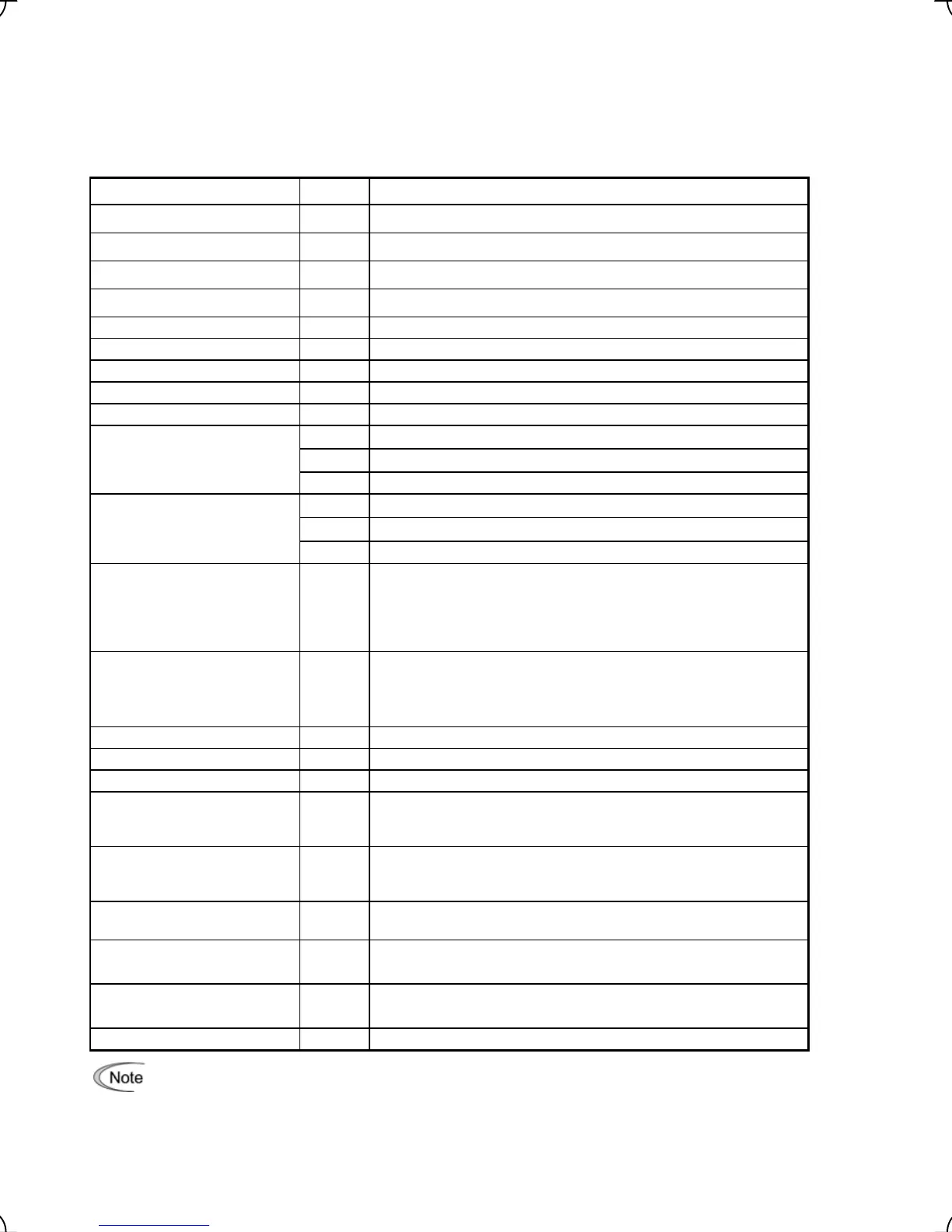
Table 3.11 Alarm Information Items
Item Symbol Description
Alarm history (last) O/1 Alarm code and the number of occurrences
Alarm history (2
nd
last) -1 Alarm code and the number of occurrences
Alarm history (3
rd
last) -2 Alarm code and the number of occurrences
Alarm history (4
th
last) -3 Alarm code and the number of occurrences
Reference speed (final) Fot1 Reference speed (final) commanded to the ASR (unit : Hz)
Output current Iout Output current value
Output voltage Vout Output voltage value
Calculated torque TRQ Reference torque
Reference speed (pre-ramp) Fref Reference speed (pre-ramp) (unit : Hz)
FWD Forward
REV Reverse
Rotational direction
Blank Stopped
IL Current limiting
LU Undervoltage detected (Inverter stopped)
Running status
TL Torque limiting
Shows the cumulative operation time during which the inverter was
powered ON.
Cumulative operation time TIME
When the total time exceeds 65,535 hours, the counter will be reset to 0
and the count will start again.
Shows the total number of startups of the motor (number of times when the
run command for the inverter was turned ON).
Number of startups NST
When the number of times exceeds 65,535 times, the counter will be reset
to 0 and the count will start again.
DC link circuit voltage EDC Shows the DC link circuit voltage of the inverter's main circuit.
Inverter internal air temperature TMPI Shows the temperature inside the inverter.
Heat sink temperature TMPF Shows the temperature of the heat sink.
Input signal information at the control circuit terminals
[FWD], [REV], [X1] to [X8], and [EN] (Highlighted when short-circuited;
normal when open)
Input status at terminal TRM
Input signal information via communications link
[FWD], [REV], [X1] to [X8], [EN], (XF), (XR), and (RST) (Highlighted when
1; normal when 0)
Input status at terminal via
communications link
LNK
Output signals information
[Y1] to [Y5], and [30A/B/C] ((Highlighted when 1; normal when 0)
Output status at terminal -
Alarm codes (2) that have simultaneously occurred
Multiple alarm 2 3
("----" is displayed if no alarms have occurred.)
Alarm codes (1) that have simultaneously occurred
Multiple alarm 1 2
("----" is displayed if no alarms have occurred.)
Alarm sub code SUB Auxiliary error code for causes of alarm
When the same alarm occurs repeatedly in succession, the alarm information for the first will be
preserved as the alarm history (2
nd
last), and last occurrence as the alarm history (last). The information
for other occurrences will be discarded. The number of consecutive occurrences will be preserved in the
alarm history (2
nd
last).
3-23