3.4.5 Checking I/O signal status -- Menu #4 "I/O Checking" --
Menu #4 "I/O Checking" in Programming mode allows you to check the digital and analog input/output signals
coming in/out of the inverter. This menu is used to check the running status during maintenance or test run.
Table 3.8 lists check items available.
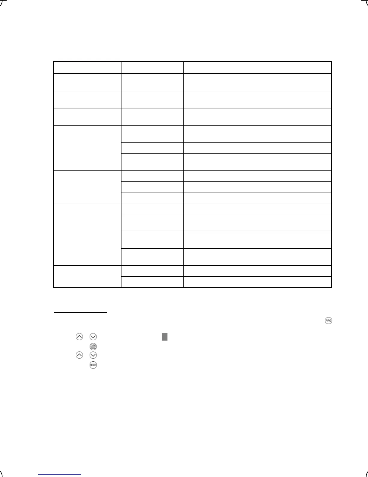
Table 3.8 I/O Check Items
Item Symbol Description
Input status at terminal FWD, REV, X1 to X8
and EN
Input signal information at the control circuit terminals
(Highlighted when short-circuited; normal when open)
Input status at terminal via
communications link
FWD, REV, X1 –to X8,
XF, XR and RST
Input signal information via communications link
(Highlighted when 1; normal when 0)
Output status at terminal Y1 to Y5 and 30A/B/C Output signal information
(Highlighted when ON; normal when OFF)
DI Input signal information at the control circuit terminals
(hexadecimal)
DO Output signal information (hexadecimal)
I/O status
(hexadecimal)
LNK Input signal information via communications link
(hexadecimal)
12 Input voltage at terminal [12]
C1 Input current at terminal [C1]
Analog input signals
V2 Input voltage at terminal [V2]
θ
e Output electrical angle
θ
re Magnet pole position detection angle
(only when the PP option is mounted)
θ
m Detected mechanical angle
(only when the PS option is mounted)
Phase angle
PPb Magnet pole position detection signal in binary
(only when the PP option is mounted)
P2 Encoder pulse frequency for A-phase and B-phase Encoder pulse frequency
Z2 Encoder pulse frequency for Z-phase
Note: FRENIC-Lift supports only symbols listed in the above table. It displays "---" for symbols not supported.
Basic key operation
(1) When the inverter is powered on, it automatically enters Running mode. In Running mode, press t e h
key to enter Programming mode. The menu for function selection will appe
ar.
(2) Use / keys to move the pointer
Æ
to "4. I/O CHECK."
(3) Press the
key to display the I/O checking screen (one out of a total of 9 pages).
(4) Use
/ keys to select the target item page and confirm the I/O check data for that item.
(5) Press the
key to go back to the menu.
Figure 3.14 shows the LCD screen transition for "4. I/O CHECK."
3-16