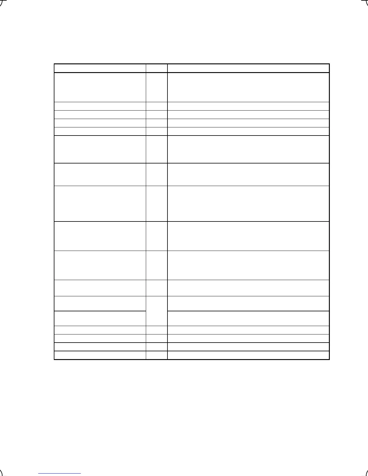
3.4.6 Reading maintenance information -- Menu #5 "Maintenance Information" --
Menu #5 "Maintenance Information" in Programming mode allows you to view information necessary for
performing maintenance on the inverter.
Table 3.10 lists the maintenance information display items.
Table 3.10 Display Items for Maintenance
Item Symbol Description
Shows the cumulative operation time during which the inverter was
powered ON.
Cumulative operation time TIME
When the total time exceeds 65,535 hours, the counter will be reset
to 0 and the count will start again.
DC link circuit voltage EDC Shows the DC link circuit voltage of the inverter’s main circuit.
Max. inverter internal air temperature TMPI Shows the maximum temperature inside the inverter every hour.
Max. heat sink temperature TMPF Shows the maximum temperature of the heat sink every hour.
Max. effective current value Imax Shows the maximum current in RMS every hour.
Shows the current capacitance of the DC bus capacitor as % of the
capacitance at factory shipment. Refer to the FRENIC-Lift
Instruction Manual (INR-SI47-1038-E), Chapter 7 "MAINTENANCE
AND INSPECTION" for details.
Internal capacitance of the DC bus
capacitor
CAP
Shows the cumulative run time of the motor.
Cumulative operation time of motor MTIM
When the total time exceeds 65,535 hours, the counter will be reset
to 0 and the count will start again.
Shows the product of the cumulative time of voltage being applied
to the electrolytic capacitor on the printed circuit board and a
coefficient determined by the environmental condition. When the
total time exceeds 65,535 hours, the counting will stop.
Cumulative run time of capacitors on
printed circuit board
TCAP
As a guide, 61,000 hours is considered as life.
Shows the cumulative run time of the cooling fan. When the total
time exceeds 65,535 hours, the counting will stop.
Cumulative run time of cooling fan TFAN
As a guide, 61,000 hours is considered as life (This number varies
with the capacity of the inverter.)
Shows the total number of startups of the motor (number of times
when the run command for the inverter was turned ON).
Number of startups NST
When the number of times exceeds 65,535 times, the counter will
be reset to 0 and the count will start again.
Shows the cumulative power consumption of the inverter.
Cumulative power consumption Wh
Upon exceeding 1,000,000 kWh, the count goes back to 0.
Number of RS485 communications
errors
Shows the cumulative number of RS485 communications
(standard) errors since first power ON.
NRR1
Contents of RS485 communications
error
Shows the latest error that has occurred with RS485
communications (standard) in a code.
*1
ROM version of the inverter MAIN Shows the ROM version of the inverter in 4 digits.
ROM version of the keypad KP Shows the ROM version of the keypad in 4 digits.
ROM version of the option OP1 Shows the ROM version of the option in 4 digits.
Option name OPC Shows the name of the option currently connected.
*1 For details of errors, refer to the RS485 Communication User’s Manual.
Note: FRENIC-Lift supports only symbols listed in the above table. It displays "---" for symbols not supported.
3-20