3.3.3 Monitoring the running status on the LED monitor
The ten items listed below can be monitored on the 7-segment LED monitor. Immediately after the power is
turned ON, the monitor item specified by function code E43 is displayed.
key in Running mode switches between monitor items in the sequence shown in Table 3.4.
Pressing the
Table 3.4 Monitor Items
Monitor
page #
Function
code E43
Unit
Monitor Items Example Meaning of Displayed Value
Speed monitor Function code E48 specifies what to be displayed. 0
r/min*
1
m/min
Hz
Reference speed
(final)
Reference speed (final) commanded to the
Automatic Speed Regulator (ASR)
(E48 = 0)
0
100
r/min*
1
m/min
Hz
Reference speed
(pre-ramp)
(E48 = 2)
2
100
r/min
Motor rotation speed (E48 = 3)
3 Motor speed
1500
m/min
5 Elevator speed Elevator speed (E48 = 5)
11!1
A
Output of the inverter in current in rms 3
8 Output current
1"34
kW
Input power to the inverter 9
9 Input power
1*25
Torque in % based on the motor rated torque
being at 100%*
2
%
10 Calculated torque
8
200
V
11 Output voltage
Output of the inverter in voltage in rms 4
25&0
Torque in % based on the motor rated torque
being at 100%
%
18
19 Reference torque
200
Torque bias balance
adjustment value
%
Used to adjust the analog torque bias balance 19
20
6$0
BTBB
Torque bias gain
adjustment value
%
21
Used to adjust the analog torque bias gain 20
40*0
BTBG
*
1
Function code C21 provides a choice of units--r/min, m/min, and Hz.
*
2
In vector control with PG, this item shows the reference torque.
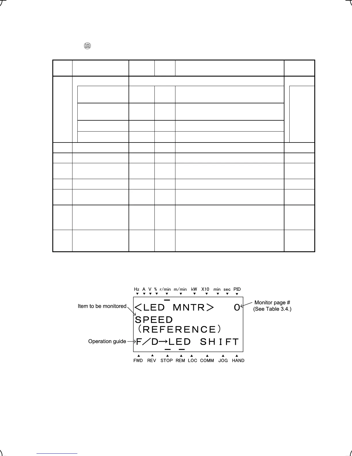
Figure 3.7 Display Sample of LED Monitor Item
3-8