FEASA LED ANALYSER
ICT VERSION
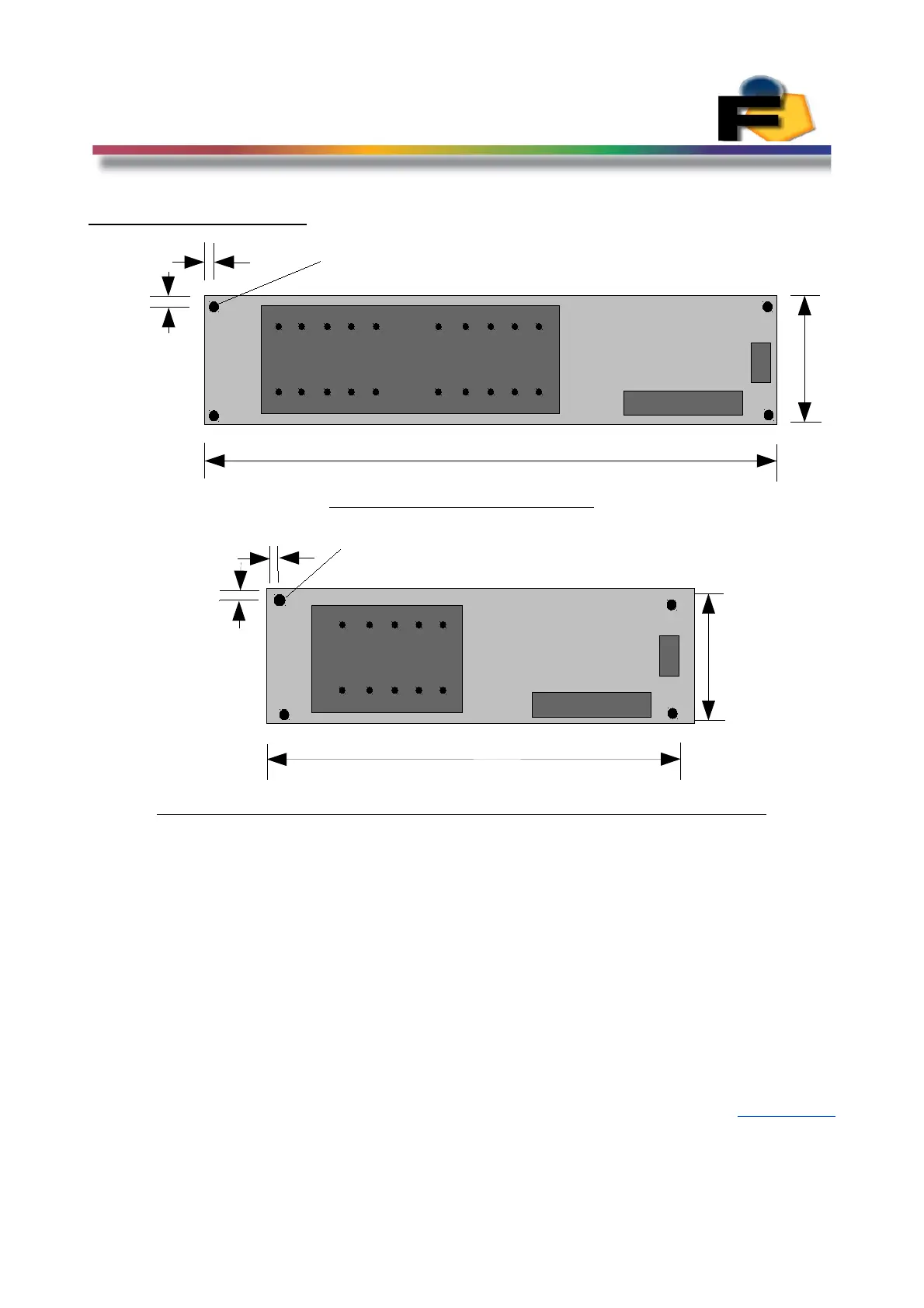
Physical Layout
Figure 6a (Feasa 20-I, 20-IB).
Figure 6b (Feasa 2-I, 3-I, 5-I, 6-I, 10-I, 2-IB, 3-IB, 5-IB, 6-IB, 10-IB)
Figure 6a shows the physical layout of the Feasa 20-I & Feasa 20-IB Analyser's
The fibers are labelled 1–20.
Figure 6b shows the physical layout of the Feasa 10-I & 10-IB Analyser's
The Fibers are labeled 1-10. Options include Feasa 2, 3, 5, 6 channel
There are four 3mm diameter Mounting holes at the corners.
The ICT Port is a 20-pin connector while the Serial Port is a 3-pin connector.
The PCB has been designed so that it can easily be fitted in the top or bottom side of a Fixture.
Please refer to the Fixturing Guidelines Manual for connector pin out details.
Back to Index
14
ICT
Serial
Fiber Block
1
10
11
20
140mm
29mm
3mm
3mm
Dia
1
2
3
1
220
19
1
2
3
Serial
Fiber Block
1
10 6
29mm
3mm
3mm
Dia
100mm
5
19 1
20 2
ICT
 Loading...