FEASA LED ANALYSER
ICT VERSION
Synchronous Serial Mode
In Circuit Test Synchronous Serial Mode
The LED Analyser can be controlled using a Synchronous Serial bus, through which commands
can be sent and the results read back for testing LED's. The Feasa ICT Analyser is shipped
with Synchronous Serial Mode enabled. This can be verified using the command getictstatus.
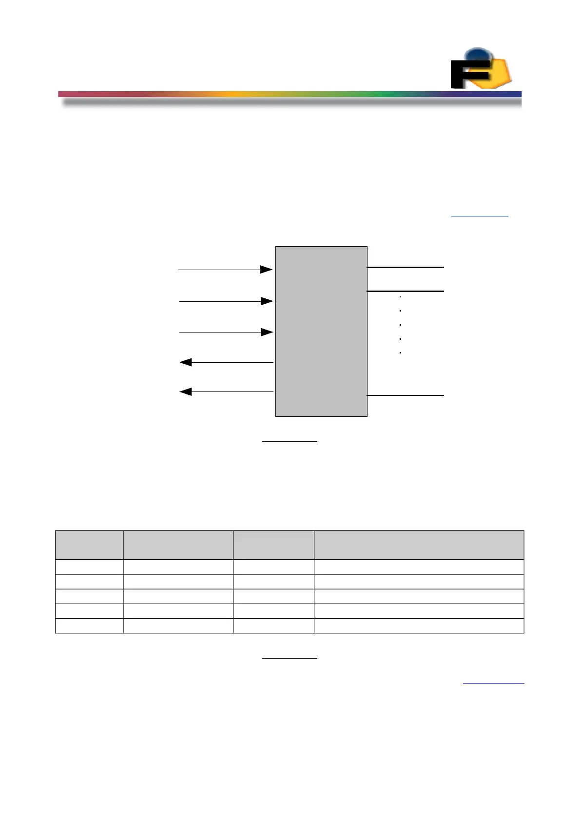
Figure 17.
Figure 17 shows a block diagram of the Synchronous serial bus. There are 5 lines used to
implement the Synchronous serial mode. These signals are described in Figure 18.
Pin
Number
Signal Input/
Output
Description
9 Addr0/LA_Select Input Used to select the Led Analyser
3 Clock Input Synchronous Clock
2 Ser_In Input Serial Data Input
1 Ser_Out Output Serial Data Output
18 RyBy_bar Output Ready Busy Status output
Figure 18.
Back to Index
32
Clock
Serial In
Serial Out
LA Select
Ready/Busy
LED
Analyser
Fiber1
Fiber2
Fiber20
9
3
2
1
18
 Loading...