FEASA LED ANALYSER
ICT VERSION
Synchronous Serial Mode
Clear Comms Buffer
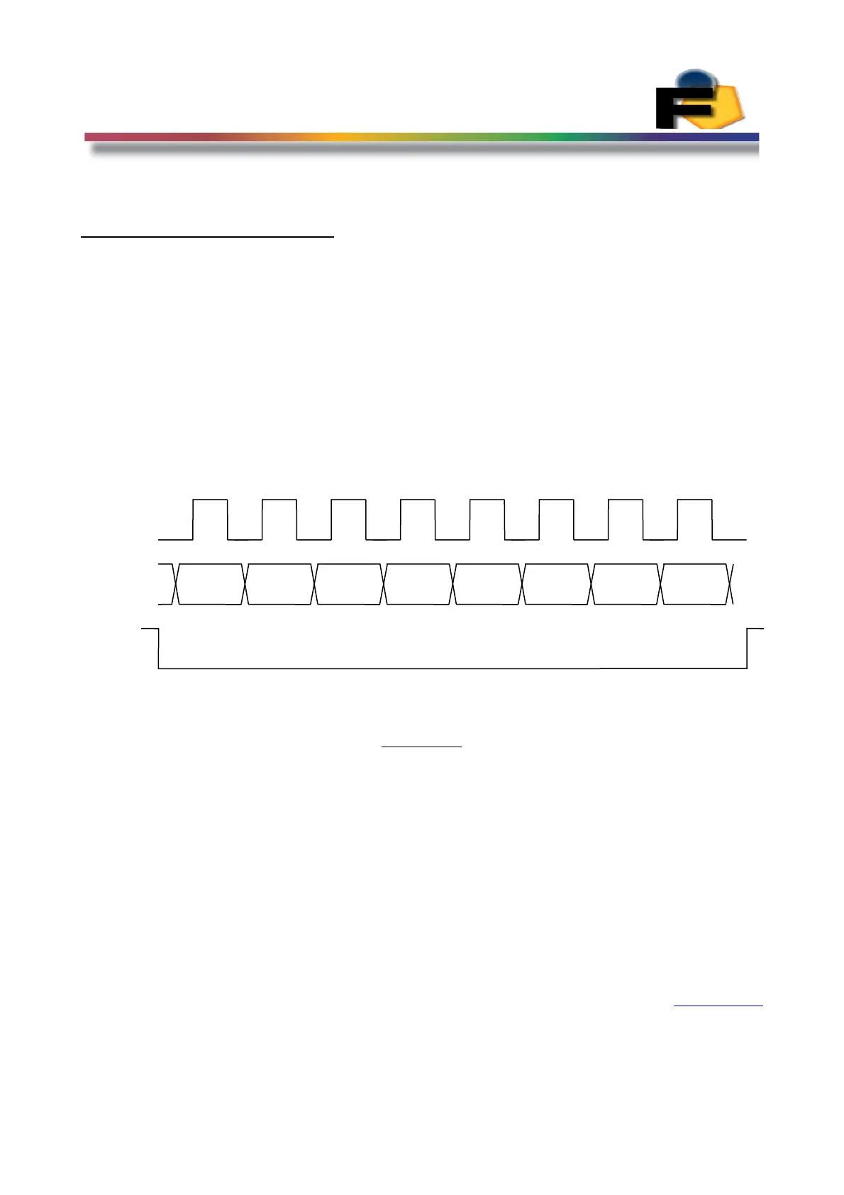
This command will clear the Communications Buffer of the Synchronous Serial Port of any data
bits. The sequence for this command is shown in Figure 20.
Binary 11111111 (0xFF) is clocked into the LED Analyser while the Addr0/LA_Select signal is
held low.
The command is clocked in on the falling edge of SCK.
Figure 20.
The signal Addr0/LA_Select must be driven low while 0xFF is clocked into the Analyser.
For all other commands the signal Addr0/LA_Select should be driven high.
Back to Index
35
SCK
0
Serial
In
LA_sele
ct
1 2 3 4 5 6 7
MSB=1
B6=1
B5=1 B4=1 B3=1 B2=1 B1=1 B0=1
 Loading...