Chapter 9 External Interface
PAGE 9-14
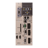
● Module Pin Configuration
Manufacturer: Phoenix Contact
Type: Connector plug
Model: MSTB 2.5/5-ST-5.08 AU M
Applicable wire size: AWG 14 ~ 23 or 0.25mm
2
~ 2.5mm
2
* The connector is provided with the equipment.
Please prepare the cable on your own.
The cable wiring method is the same as that for the control power. Please refer to “Control Power Wiring
Procedures” of “Input Power Source Connection” on PAGE 3-4 of the <<AFC3000 AC Servo Nutrunner
Instruction Manual>>.
However, the compatible wire size and recommended rod terminals (ferrules) are as follows.
・ Compatible wire size ・・・ AWG 23 ~ 14 (0.25mm
2
~ 2.5mm
2
)
・ Recommended rod terminals (ferrules)
・・・ Model: AI 2,5-6 WH (Phoenix Contact)
・ Be sure to connect the cable with all power being OFF.
Also, the module LEDs indicate the states of the nodes of the AFC3000 CC-Link System and the network
state.
● List of LED Indications
Power is not supplied or connection is unestablished.
A critical error has occurred.
A critical error has occurred.
A cyclic redundancy check (CRC) error has occurred.
Station No. or baud rate setting is changed after power on.