Chapter 6 Description of Operations
PAGE 6-5
6-2 RUN Mode
When the power is activated (turned ON) and the initial process ends, the operation enabled mode
(RUN mode) is entered. In the RUN mode, mainly the fastening results, abnormality status, Axis No.,
parameters, etc., are indicated.
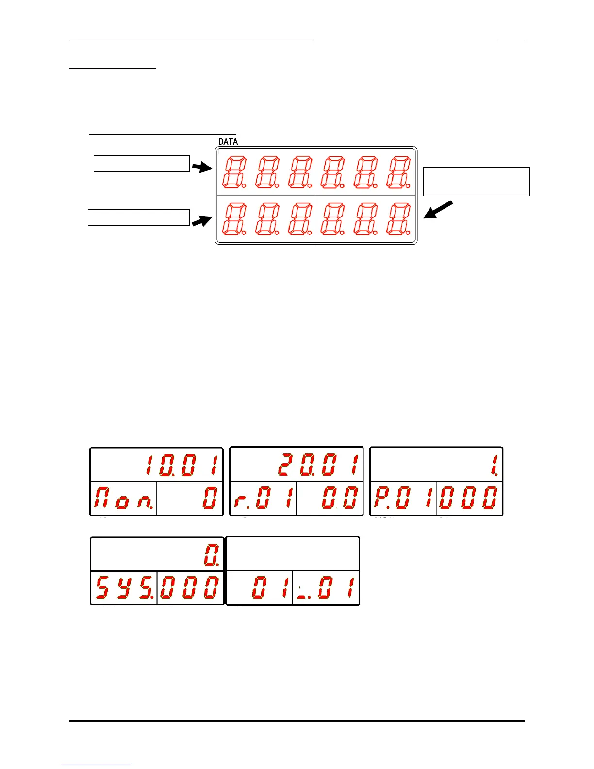
Data Indication Part (RUN Mode)
DATA Indication Part
In the real time mode, fastening result mode, and parameter (system) setting mode, the fastening
result, set value (parameter), or executed value is indicated here as designated by the
COUNT/D-No. indication part.
WORK Indication Part
The WORK No. is indicated here (if sequence operation is disabled, the parameter No. is
indicated). When an error occurs, the abnormal state No. is indicated in the operation view.
COUNT/D-No. Indication Part
In the real time mode, fastening result mode, and parameter (system) setting mode, the No. of the
data indicated in the DATA indication part is indicated.
Also in the operation view, the current speed state is indicated during the fastening operation and
the current cycle count value (C##) is indicated when the fastening operation is not started. The
abnormal state No. sub code is indicated when an error occurs.
■Real Time Mode ■Fastening Result Mode ■Parameter Setting Mode
■System Setting Mode ■Operation View
Please refer to the following pages concerning the respective modes in the RUN mode.