Chapter 4 Installation
PAGE 4-18
4-6 External Monitoring Device Signal
External monitor signals are output from the MONITOR connector on the controller bottom.
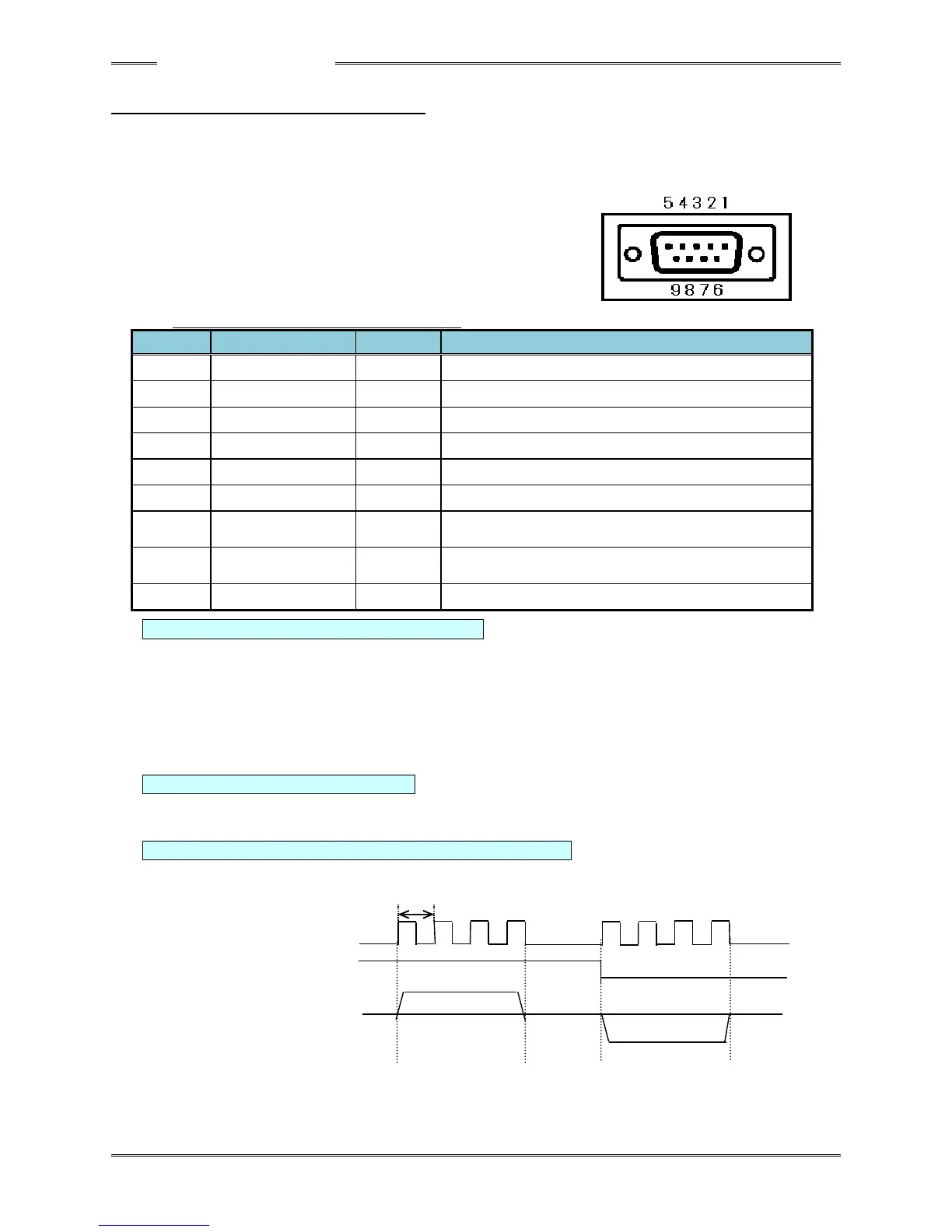
Compatible connector
D-SUB 9-pin plug Inch thread (#4-40)
External monitor signal specifications
TORQUE OUT: Torque Analog Voltage Signal
With the monitor voltage, the range from the ZERO voltage to the CAL voltage at the calibration
torque is expressed by a potential difference of approximately 3.75V. The ZERO voltage is the
voltage in the state where the tool is stopped. *The ZERO voltage is not 0V (within a range of -0.1V
~ +0.1V). Also, even among tools of the same model, the ZERO voltage differs according to each
tool.
(Example) If the ZERO voltage is -0.03V, the CAL voltage at the calibration torque is +3.72V and the
voltage change is Δ3.75V.
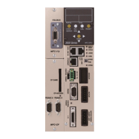
ANGLE PULSE: Angle Pulse Signal (5V TTL signal)
As the angle pulse, 1 pulse is output per 1 degree.
*There is some error with respect to the actual rotation angle (1 rotation of the tip: 358 ~ 362 pulses).
ANGLE CW/CCW: Normal/Reverse Rotation Pulse Signal (5V TTL signal)
A HI signal is output when the motor is rotating in the normal direction and a LOW signal is output
when the motor is rotating in reverse.