45
OPERATION
Operation_Pic_number:1
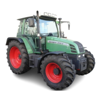
Maximum length is reached when the marking
(arrow) is visible.
17.3 Mechanical lateral locking
Operation_Pic_number:1
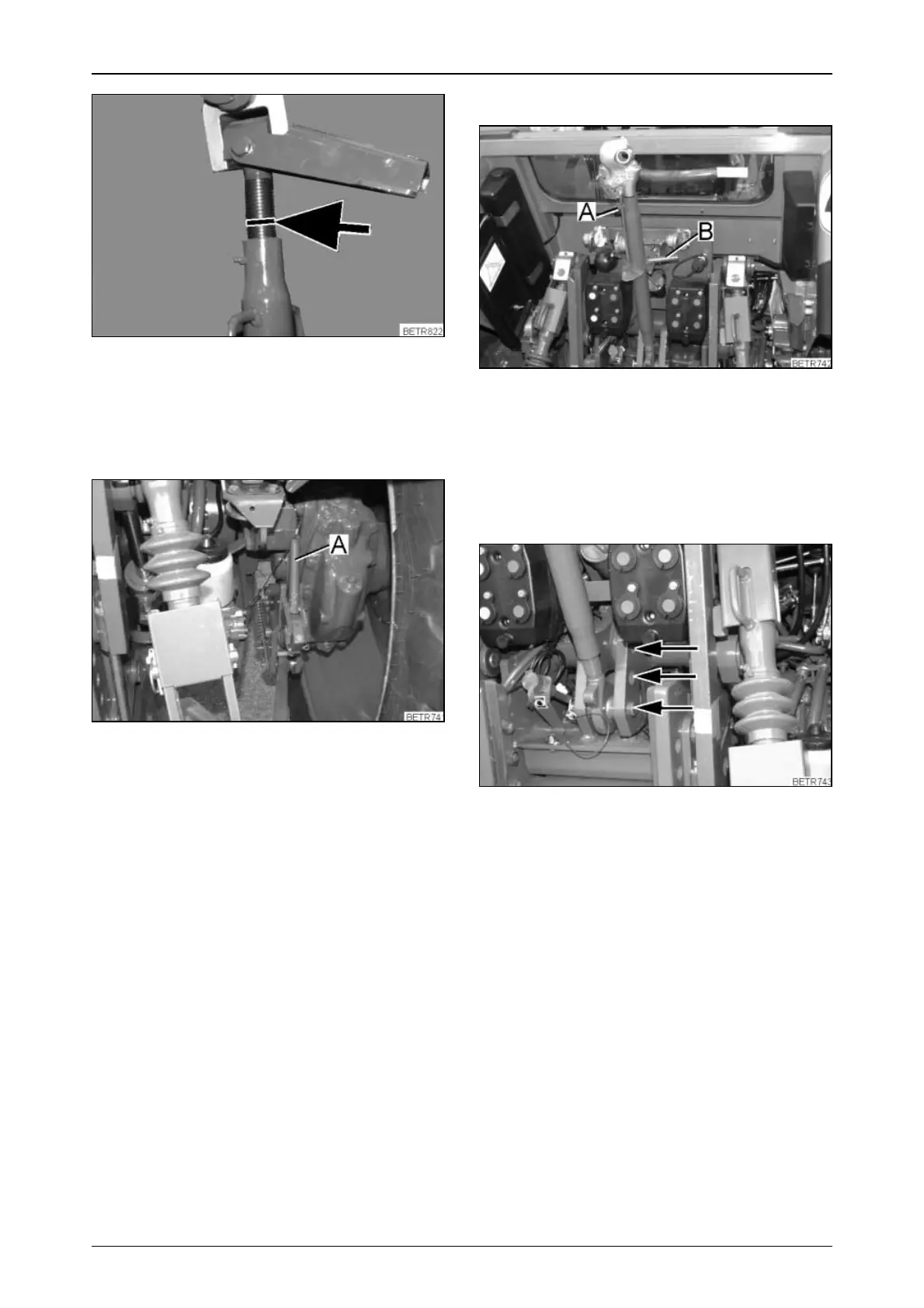
Lock the lower links using both the left and right
levers (A).
For rigid implement:
● Move levers upwards.
Implement with lateral movement:
● Move levers downwards.
Fig.81
Fig.82
17.4 Top link
Operation_Pic_number:1
● Adjust length by turning handle (B).
Both threads must be adjusted equally. Make
sure the securing clamp can be folded over the
stub.
Mounting on tractor
Operation_Pic_number:1
Can be fastened to three bore holes (for better
implement adaptation and for increased lifting
power).
For increased lifting power and reduced
sensitivity of control hydraulics:
● Fit top link in upper hole.
For reduced lifting power and increased
sensitivity of control hydraulics:
● Fit top link in lower hole.
Fig.83
Fig.84