89
CARE AND MAINTENANCE
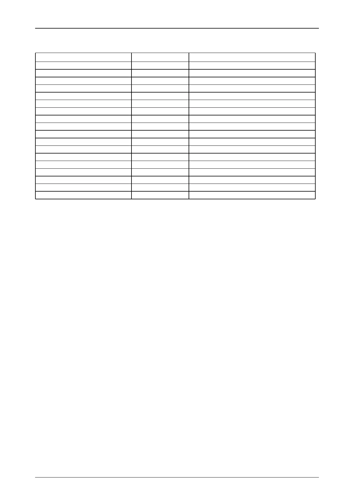
21.2 Colour identification for electric wires
Text-module
21.3 Circuit diagrams
Text-module
List of circuit diagrams
Sheet 2 = Cab
Sheet 3 = Engine
Sheet 4 = Transmission
Sheet 5 = Driver status
Sheet 6 = Driver status EPC
Sheet 8 = Front/rear PTO
Sheet 9 = Switch for 4-WD / differential lock
Sheet 10 = Splitter range control
Sheet 11 = Power supply for electronic boxes
Sheet 12 = Power supply + UB and starter motor control
Sheet 13 = Flasher unit
Sheet 14 = Lighting STVZO
Sheet 15 = Wipers and rotating beacon
Sheet 16 = Cold-start system
Sheet 17 = Engine switch-off
Sheet 18 = Dashpanel
Sheet 19 = Central instrument
Sheet 20 = Electro-hydraulic power lift control
Sheet 21 = Horn
Sheet 22 = Brake light
Sheet 23 = Work lamps rear
Sheet 24 = Front work lamp
Sheet 25 = Ventilation and air conditioning
Sheet 26 = Heated rear windscreen
Sheet 27 = Interior cab lighting and radio
Sheet 28 = Open socket separation point, 3rd hydraulic circuit, hydraulic summation
Sheet 29 = Heater
Sheet 30 = Connector A
Sheet 31 = Connector C
Sheet 32 = Connector D
Sheet 33 = Connector E
Colour of wire Abbreviation Mark
White (with black printing) ws General colour
red rt + UB 30
black sw + UB 15
yellow ge + UB 15E
grey (basic lighting colour) gr + UB 58
grey - black gr-sw + UB 58 lighting left
grey - red gr-rt + UB 58 lighting right
yellow ge + UB power supply
brown br Body earth
brown - white br-ws Earth electronics
brown - yellow br-ge Earth sensors
black - green sw-gn Direction indicator right
black - white sw-ws Direction indicator left
orange or Additional wiring
blue bl
pink rs
turquoise tk
violet vi