3. Mounting and installation
Festo P.BE-CMMS-FHPP-DN-SW-EN en 1103a 13
3. Mounting and installation
3.1 Mounting
Caution
The motor controller must be disconnected from all current carrying
cables before an additional module is fitted. After switching off the
operating voltage, you must wait 1 minute before the capacitors in
the motor controller are fully discharged.
Caution
Make sure that measures for ESD protection are taken when
handling the additional module.
Use a suitable screwdriver to remove the front cover over module shaft Ext1 of the motor
controller. The additional module is now placed in the open module shaft so that the
printed circuit board slides into the guides on the sides of the module shaft. Push the
board in as far as possible. The front plate of the additional modue is then screwed to the
motor controller housing with a Philips screw. Make sure that the front plate fits flush with
the front in order that it has conductive contact with the housing.
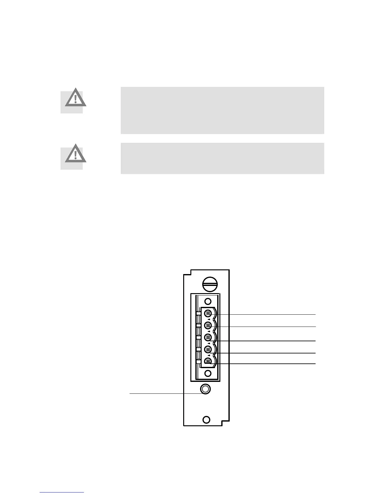
3.2 Installation
1 Pin 1: V-
2 Pin 2: CAN_L
3 Pin 3: Drain / Shield
4 Pin 4: CAN_H
5 Pin 5: V+
6 MNS LED
Fig. 3.1 DeviceNet module - pin assignment
On the CMMS/CMMD motor controllers the DeviceNet interface has been designed in the
form of an optional additional module. An open connector with 5 connections is accessible