© 2008 Festo Corporation 35 U
Getting Started with Festo MecLab
Stack Magazine Station
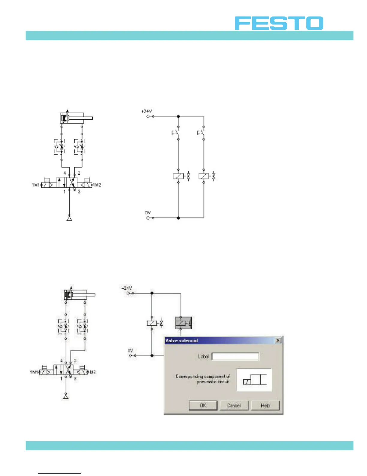
This produces a circuit diagram like that shown in Figure 4.15.
Figure 4.15: Wiring of the electrical circuit
Remember to assign the same label to the components that are located in both the electrical
schematic and the pneumatic diagram (for example the “valve” solenoid in the pneumatic dia-
gram and the electrical solenoid “coil” in the electrical schematic) otherwise the circuit will
not operate correctly.
Figure 4.16: Inserting labels for the valve solenoids
 Loading...