© 2008 Festo Corporation 72 U
Getting Started with Festo MecLab
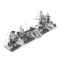
Handling Station
Step 9: Create the control program
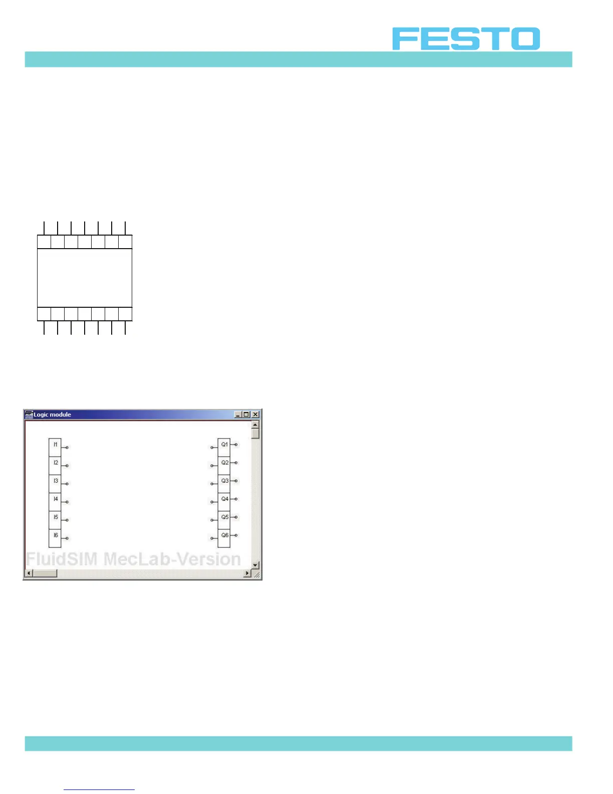
The figure below is a control module. It is called a “Logic Module” in the FluidSim library.
In order to “write” a program in this module you must first “enter” the module by double
clicking on it. A new window containing the digital module's input and output channel will be
displayed.
Figure 6.13: Input and output channel inside the logic module
Inputs marked I1 to I6 are located on the left side. Outputs marked Q1 to Q6 are located on
the right. Inputs and outputs are linked using logic devices (these are located in the same
part of the library as the logic module).
The devices are inserted in the program like all other components. Left click, hold and drag
the component to the program, then release.
Q3 Q4 Q5 Q6
0V Q1 Q2 Q3 Q4 Q5 Q6
24V I1 I2 I3 I4 I5 I6
 Loading...