© 2008 Festo Corporation 73 U
Getting Started with Festo MecLab
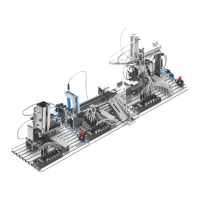
Handling Station
The task requires that the cylinder retract or extend when the respective pushbutton is
pressed and
the cylinder has reached the relevant end position:
1. Valve solenoid 1M1 is switched on when pushbutton S1 and proximity sensor 1S1 are ac-
tuated.
Valve solenoid 1M2 is switched on when pushbutton S2 and proximity sensor 1S2 are actu-
ated.
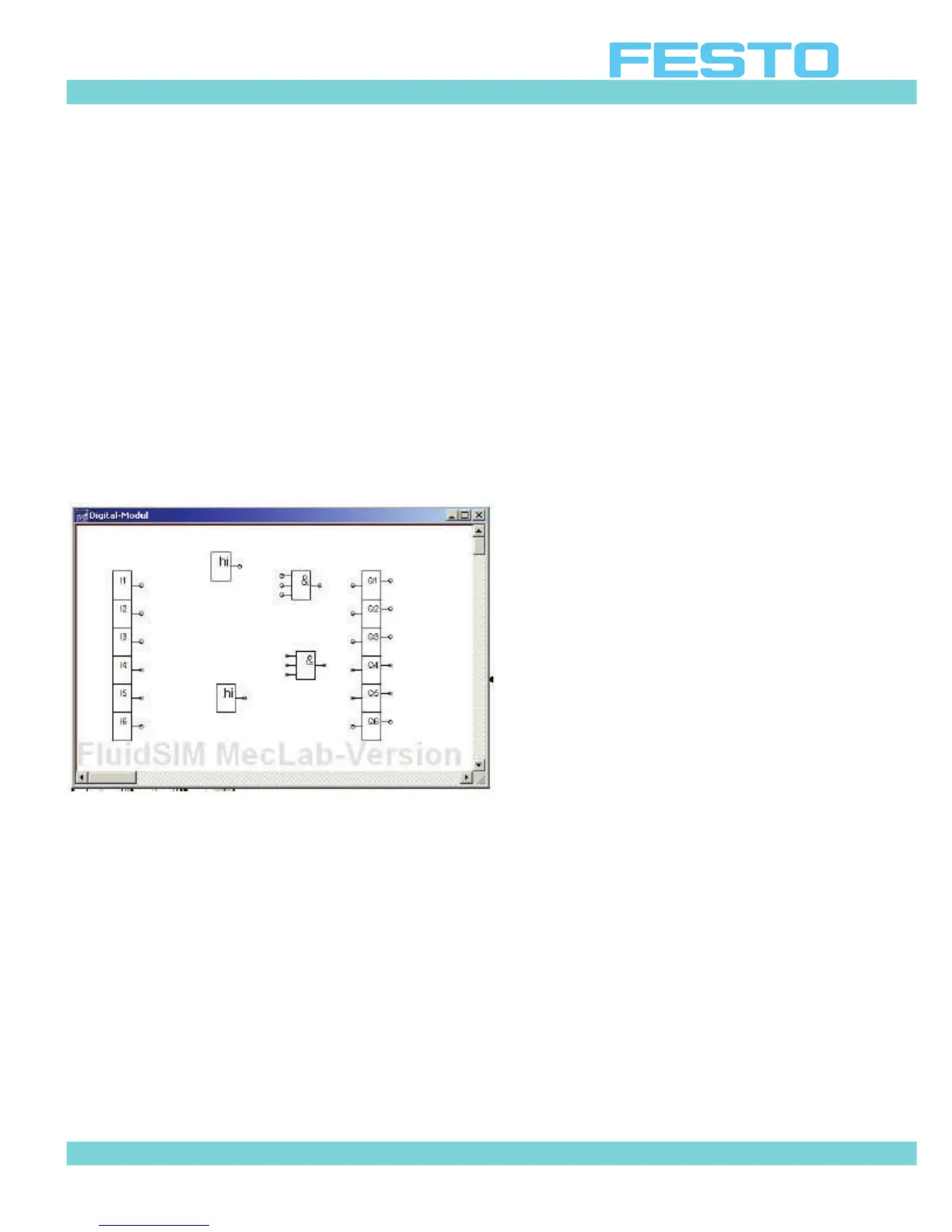
This means that two AND gates are needed in the program. Since the AND gate in FluidSIM®
has three inputs, two high gates are used so that the third, redundant one can always be set
to high. Otherwise FluidSIM® would issue an error message that there is one unassigned in-
put.
Figure 6.14: Digital module with logic gates
Note
Unused AND gate inputs must be provided with a signal. Use a “Hi” symbol and connect to
the unused input.
The logic gates are now connected and the logic program is completed (cf. Figure 6.15).
Closing the input window stores the program in the digital module (or PLC). The simulation
can be started after the window closes.
 Loading...