© 2008 Festo Corporation 65 U
Getting Started with Festo MecLab
Handling Station
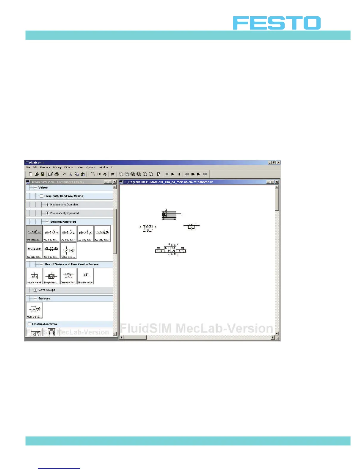
The pneumatic system consists of :
1. One double-acting cylinder
2. One 4/2-way double-solenoid valve
3. Two one-way flow control valves
4. One compressed air supply
Figure 6.5 shows the components in the workspace.
Figure 6.5: Components of the pneumatic circuit diagram
 Loading...