© 2008 Festo Corporation 44 U
Getting Started with Festo MecLab
Conveyor Station
Solution
The solution involves four steps:
1. Create the mechanical setup
2. Create the circuit diagrams and programming in FluidSIM®
3. Test the program via simulation
4. Test the program with the conveyor station
Step 1: Create the mechanical setup
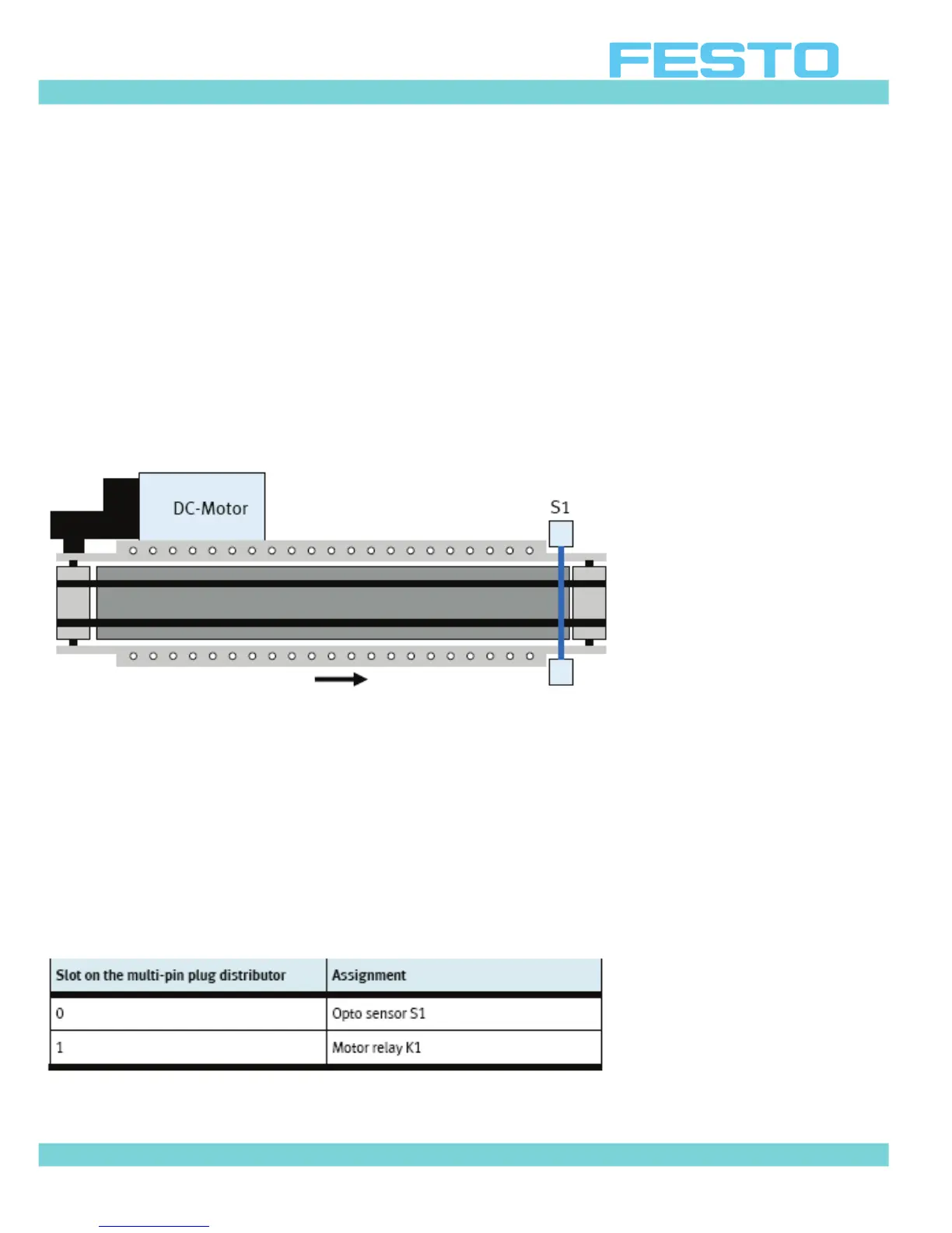
Figure 5.2: Schematic diagram of the conveyor
Figure 5.2 is a schematic diagram of the conveyor as it is required for the task. It shows the
arrangements of the components. It is important to understand a systems layout in order to
plan and design the control program.
The optical sensor (through-beam sensor) must be mounted at the end of the conveyor using
the enclosed tool.
Since they will not be used, remove the stopper and the slide.
The following table provides an overview of the wiring at the multi-pin plug distributor:
Table 5.1: Pin assignment on the multi-pin plug distributor
 Loading...