Reproduction forbidden without Fibocom Wireless Inc. written authorization - All rights reserved.
FIBOCOM MC610 Series Hardware Guide 29/70
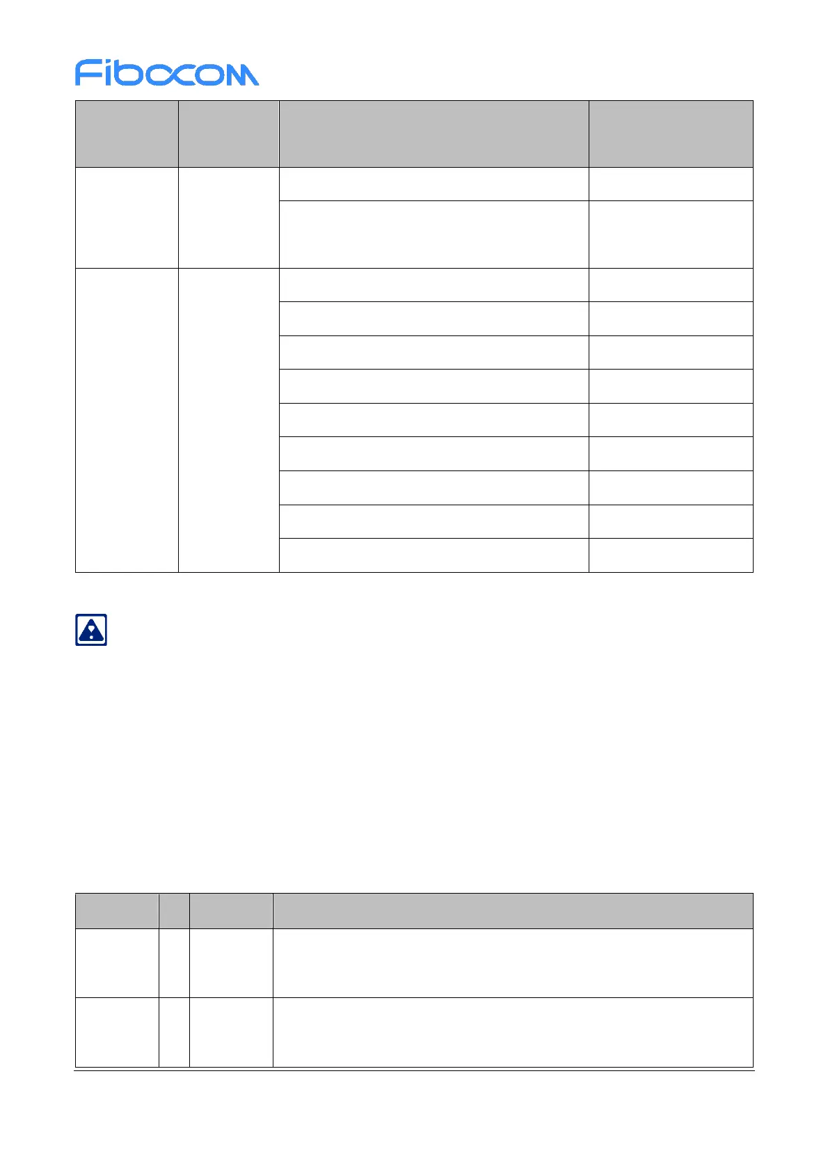
GPRS Data transfer PCS1900; PCL=0;
1Rx/4Tx
LTE FDD Data transfer Band 1 @+23dBm
LTE FDD Data transfer Band 2 @+23dBm
LTE FDD Data transfer Band 3 @+23dBm
LTE FDD Data transfer Band 4 @+23dBm
LTE FDD Data transfer Band 5 @+23dBm
LTE FDD Data transfer Band 7 @+23dBm
LTE FDD Data transfer Band 8 @+23dBm
LTE FDD Data transfer Band 28 @+23dBm
LTE FDD Data transfer Band 66 @+23dBm
The above results are laboratory test data, with a deviation of ±10%.
3.3 Control Signal
MC610 series modules provide 2-channel control signals to start up/shut down and reset the module. The
pin definition is defined as shown in the following table:
Table 3-6 Control signal
When the module is working, provide RESET with a Tst (100 ms) low
level, and then rise, reset the module.
The minimum duration of low level is 2 s when it is started up at a low
level, and 3.1 s when it is shut down at a low level.
 Loading...
