EasyManuals Logo

Fibocom MC610 Series User Manual

Fibocom MC610 Series
70 pages
To Next Page IconTo Next Page
To Previous Page IconTo Previous Page
Page #48 background imageLoading...
Page #48 background image
Reproduction forbidden without Fibocom Wireless Inc. written authorization - All rights reserved.
FIBOCOM MC610 Series Hardware Guide 48/70
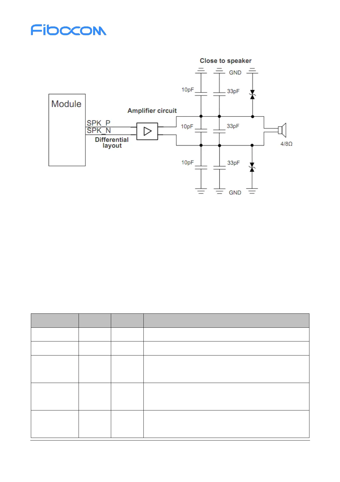
Figure 3-18 Reference circuit of Audio Power Amplifier Output
3.11 Camera Interface
MC610 supports two camera interfaces, SPI and MIPI.
The following table describes the pin description of the CAMERA interface:
Table 3-22 CAMERA interface
Pin name
I/O
Pin
Description
CAM_REFCLK
O
80
CAMERA CLK signal
CAM_PWDN
O
79
CAMERA POWER DOWN signal
CSI_D0N
I/O
92
CAMERA MIPI data D0 negative terminal;
CAM_SI1 SPI CAM serial data signal 1
CSI_D0P
I/O
91
CAMERA MIPI data D0 positive terminal;
CAM_SCK SPI CAM serial clock signal
CSI_CKN
O
90
CAMERA MIPI clock CLK negative terminal;
CAM_RSTL SPI CAM reset signal

Questions and Answers:

Question and Answer IconNeed help?

Do you have a question about the Fibocom MC610 Series and is the answer not in the manual?

Fibocom MC610 Series Specifications

General IconGeneral
BrandFibocom
ModelMC610 Series
CategoryComputer Hardware
LanguageEnglish

Related product manuals