Reproduction forbidden without Fibocom Wireless Inc. written authorization - All rights reserved.
FIBOCOM MC610 Series Hardware Guide 53/70
The antenna is a sensitive device and is easily affected by the external environment. For example, the
position of the antenna, the occupied space, and the surrounding grounding may affect the performance
of the antenna. In addition, the RF cable connected to the antenna and the fixed antenna position will also
affect the antenna performance.
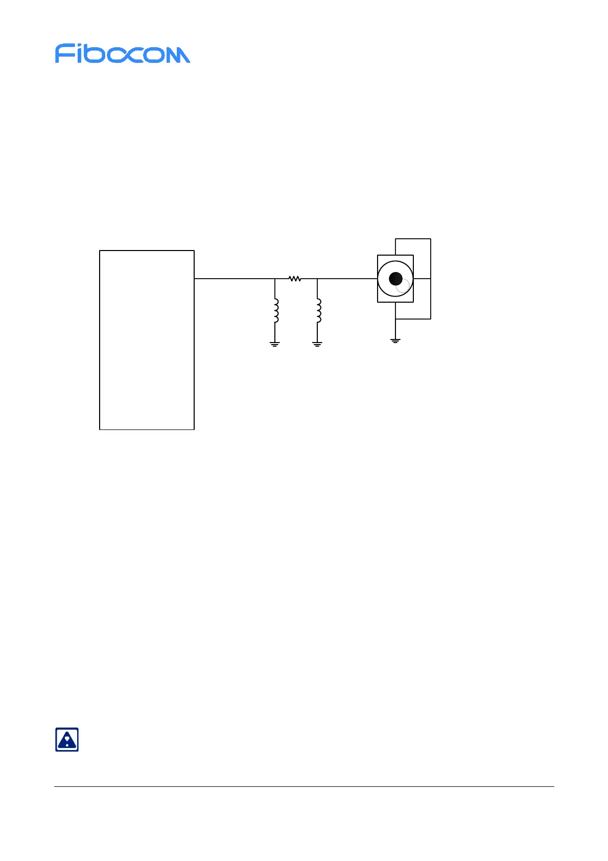
Figure 4-1 shows the reference circuit design of the main set antenna. These matches need to be placed
close to the antenna:
Figure 4-1 RF Reference circuit design
l Ensure that the characteristic impedance of the transmission line is 50 Ω.
l As the antenna line loss is less than 0.3 dB, keep the PCB routes as short as possible.
l PCB LAYOUT avoids passing through holes and overturning layers as much as possible, and also
right-angle and acute-angle route.
l There should be a good reference ground around the PCB routes to avoid other signal lines close to
the antenna.
l It is recommended to use intact formations as reference ground.
l The ground around the antenna strengthens the connection with the main ground.
Refer to FIBOCOM Design Guide_RF Antenna for detailed design.
1.5nH
NC NC
Module
ANT_MAIN
Main Antenna
 Loading...
