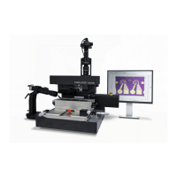
FINEPLACER
®
lambda
Rev-Nr. 1.1
Used to view alignment of component and substrate and
to adjust FINEPLACER
®
Parallelism fine adjustment screw
Rotates the tool around the x-axis to compensate an
angular deviation between tool and working plain
Locking screws for the parallelism adjust (19)
Fits into head receiver (25) and is locked with screw
(21), holds component to mount
The figure shows a Heated Pick and Place Tool with
Cooling for the Heated Pick and
Place Tool
Outlet for compressed cooling air
Plug for the Heated Pick and Place
Tool
Connector plug to the socket of the corresponding
Control Box
Placement head screw of the
Placer Arm
Locks placement head (20) in the head receiver (25)
Pipette (with automatic vacuum
switch-over)
Vacuum pickup device for moving component to and
from a tray and vice versa
Holds the placement head (20) at the placer arm.
25-pin Sub D electrical connector
(mounted plug)
Provides electrical power to the lighting devices and to
the magnet of the base plate.
Holds component in position during alignment and
placement
Connection between placer arm and Placer Control Box
(39), socket (66)
Holds a substrate, a substrate support plate or a heating
plate. Floats on air cushion above the base plate (70) for
Beam splitter optics holder
see 4.2.3
Mirror adjustment screws (y)
see 4.2.3
Move the image of the component up & down (y)
relating to the image of the substrate
Mirror adjustment screw (x)
see 4.2.3
Moves the image of the component left & right (x)
relating to the image of the substrate
Release button for front track
Locks or releases front track (23) of positioning table
25-pin Sub D Placer Control Box
panel socket
Electrically connects control box (39) to support arm
(71) via connector (26)
Controls all electronic, lighting, vacuum and air
cushion/magnet requirements of the FINEPLACER
®
Base
Module's placement and control functions. Features
mains power switching for optional modules
Target Lamp intensity knob
NACTIVE IF CONNECTED TO THE
LAMBDA
,
used to control the brightness of the lamps
Head vacuum male connector
(Vacuum filter at vacuum hose,
Connects vacuum hose to head vacuum female
connector (46) at the rear of the Placer Control Box (39)
to provide vacuum to head receiver (25)
To accept arm vacuum filter (44)
Vacuum fine adjusting valve
Vacuum fine regulation for the recognition of
components at the used placement head
See operating instructions of chapter 3.4.3