110 MS-9600LS Series Manual — P/N 52646:B8 11/20/2015
Programming Master Programming Level
ANN-LED Options
Pressing 2 for Module Options while viewing ANN-BUS Address Screen when the ANN-LED
option is selected will display the following screen:
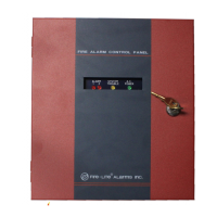
The first screen indicates that the ANN-LED at the selected ANN-BUS address is programmed to
annunciate Alarms, Supervisories and Troubles for SLC Loop #1 addressable Detectors with
addresses 1 through 10. The programming can be changed using ANN-LED Address Screens 2
and 3.
Pressing 1 while viewing ANN-LED Address Screen #2 will program the annunciator module to
annunciate either Point (addressable device address) information or Zone information.
Pressing 2 while viewing ANN-LED Address Screen #2 will program the annunciator module to
annunciate only Alarms for addressable device addresses 1-30 or Alarms, Supervisories and Trou-
bles for addressable device addresses 1-10.
Pressing 1 while viewing ANN-LED Address Screen #3 will select the Point or Zone range to be
annunciated (refer to the tables in “ANN-LED Zone Option - Alarm Only (for use with ANN-
RLED module)” on page 110 and “ANN-LED Point Option - Alarm Only (for use with ANN-
RLED module)” on page 112).
Pressing 2 while viewing ANN-LED Address Screen #3 will select either addressable detectors or
addressable modules to be annunciated.
Pressing 3 while viewing ANN-LED Address Screen #3 will select the SLC loop with the address-
able devices to be annunciated.
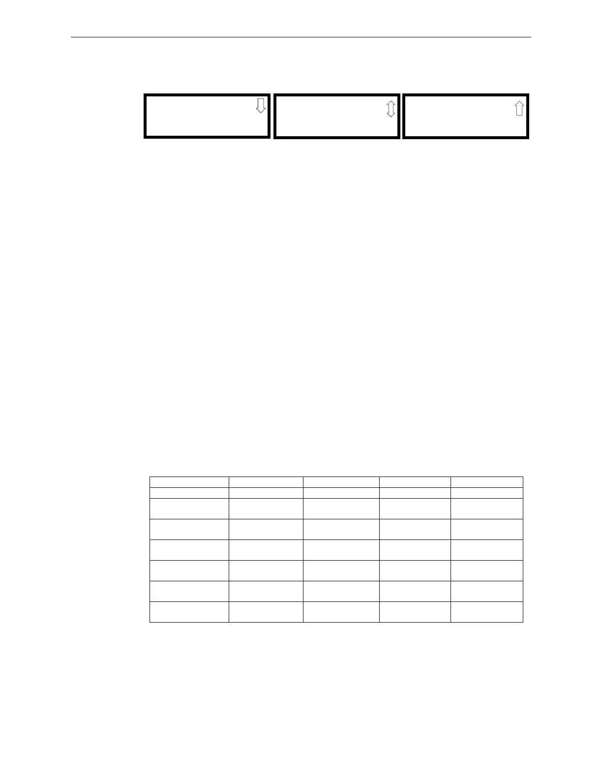
ANN-LED Zone Option - Alarm Only (for use with ANN-RLED module)
If Zone is selected as the module option, and the module is programmed to annunciate alarms only,
the first ten LEDs on the first ANN-LED module will display the system status information. The
remaining 30 LEDs on the first module and the last 30 LEDs on the remaining modules will display
the active/alarm status of each zone in the Zone Range programmed for that particular module. The
LED assignments for each ANN-LED module will be as follows.
Alarm Silenced NAC 1 Fault NAC 2 Fault NAC 3 Fault NAC 4 Fault
Earth Fault Battery Fault Charger Fault Disabled Maintenance
Zone 00
Active/Alarm
Zone 01
Active/Alarm
Zone 02
Active/Alarm
Zone 03
Active/Alarm
Zone 04
Active/Alarm
Zone 05
Active/Alarm
Zone 06
Active/Alarm
Zone 07
Active/Alarm
Zone 08
Active/Alarm
Zone 09
Active/Alarm
Zone 10
Active/Alarm
Zone 11
Active/Alarm
Zone 12
Active/Alarm
Zone 13
Active/Alarm
Zone 14
Active/Alarm
Zone 15
Active/Alarm
Zone 16
Active/Alarm
Zone 17
Active/Alarm
Zone 18
Active Alarm
Zone 19
Active/Alarm
Zone 20
Active/Alarm
Zone 21
Active/Alarm
Zone 22
Active/Alarm
Zone 23
Active/Alarm
Zone 24
Active/Alarm
Zone 25
Active/Alarm
Zone 26
Active/Alarm
Zone 27
Active/Alarm
Zone 28
Active/Alarm
Zone 29
Active/Alarm
ANN-RLED Module #1
ANN-LED - ADDR. #
LOOP1 DET 1-10
ALARM,SUPERV,TBL
ANN-LED Address Screen #1
ANN-LED - ADDR. #
1=POINT/ZONE
2=ALARM/ATS
ANN-LED Address Screen #2
ANN-LED - ADDR. #
1=RANGE
2=DET/MOD
3=LOOP#
ANN-LED Address Screen #3